
User Guide


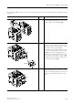


Table Of Contents
- 3 3RT1 contactors/ 3RH1 control relays
- 3.1 Specifications/regulations/approvals
- 3.2 Device description
- 3.3 Application and areas of use
- 3.3.1 3RT10 contactors with 3 main contacts for switching motors
- 3.3.2 3RT14 contactors with 3 main contacts for switching resistive loads (AC-1)
- 3.3.3 3RT12 Vacuum contactors
- 3.3.4 3RT13 and 3RT15 contactors with 4 main contacts
- 3.3.5 3RT16 capacitor contactors
- 3.3.6 Contactors with an extended operating range
- 3.3.7 3RH1 control relays
- 3.3.8 3RT10 contactor relays for switching motors (interface) and 3RH11 control relays for switching auxiliary circuits
- 3.3.9 3RA13 Contactor combinations for reversing
- 3.3.10 3RT14 Wye-delta combinations

3RT1 contactors/3RH1 control relays
SIRIUS System Manual
GWA 4NEB 430 0999-02 DS 01
3-55
Assembly kits for con-
tactor combinations
The following accessories are components of the self-assembly kits and
they are described in the diagrams of the relevant kit:
• side mount mechanical interlock
• Mechanical connectors
• Wiring modules
Assembly kits for
reversing combinations
The following table shows you the components of the kit for the contactor
combination for reversing in frame size S00 and explains how to put it
together:
Electrical interlock Note
Contactors with an NC contact in the basic unit (3RT101.) are required for
the electrical interlock.
Drawing: frame size S00 Step Procedure
1/2/3 Mount the mechanical inter-
lock between the two contac-
tors.
4/5 Press the two connecting clips
from above and below onto
the two contactors.
6 Attach the wiring modules to
connect the main conducting
paths and to electrically inter-
lock the two contactors
(3RT10.1). Make sure that the
wiring modules are flush with
the contactor at the side.
Table 3-20: Assembling the contactor combination for reversing (frame size S00)
5
4
1
3
2
6
6