
User Guide


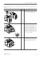


Table Of Contents
- 3 3RT1 contactors/ 3RH1 control relays
- 3.1 Specifications/regulations/approvals
- 3.2 Device description
- 3.3 Application and areas of use
- 3.3.1 3RT10 contactors with 3 main contacts for switching motors
- 3.3.2 3RT14 contactors with 3 main contacts for switching resistive loads (AC-1)
- 3.3.3 3RT12 Vacuum contactors
- 3.3.4 3RT13 and 3RT15 contactors with 4 main contacts
- 3.3.5 3RT16 capacitor contactors
- 3.3.6 Contactors with an extended operating range
- 3.3.7 3RH1 control relays
- 3.3.8 3RT10 contactor relays for switching motors (interface) and 3RH11 control relays for switching auxiliary circuits
- 3.3.9 3RA13 Contactor combinations for reversing
- 3.3.10 3RT14 Wye-delta combinations

3RT1 contactors/3RH1 control relays
SIRIUS System Manual
GWA 4NEB 430 0999-02 DS 01
3-51
Auxiliary contact
elements
Different auxiliary switches can be attached (at the front or the side) to the
3RA1 reversing combination. An integrated auxiliary switch contact is avail-
able in frame size S00.
Accessories The following accessories for the basic units can also be used for contactor
combinations for reversing:
• Auxiliary switch blocks (at the front/side)
• Surge suppressors
• Soldering pin adapters (frame size S00)
The following accessories are designed specifically for contactor combina-
tions for reversing:
• Locking devices for mechanical interlocking
• Locking devices for mechanical and electrical interlocking (at the front/
side)
• Terminals for contactor coils (for frame sizes S0 to S3)
• Mechanical connectors
• Wiring modules
Te r m i n a l s fo r
contactor coils
To reach the coil terminals A1 and A2 of the frame sizes S2 and S3 reversing
contactor combinations more easily, you can use extension terminals for
contactor coils.
For each combination, 2 x A1 and 1 x A2 are required.
Wiring module Wiring modules are available to enable you to carry out different types of
wiring (Dahlander wiring, for example).
You can find out how to mount the wiring modules in the diagrams of the
self-assembly kits.
Mechanical
interlocking
Mechanical interlocking (for frame sizes S0 to S3) is available in 2 variants:
• Attachable at the front (contactor spacing: 0 mm)
• Attachable at the side with integrated NC contact for electronic interlock-
ing
• S6 to S12: attachable at the side (no height adjustment necessary)
Note
If you want NC contact interlocking, you must use contactors with 1 NC
contact in the basic unit with the 3RT1 contactors of frame size S00.