
User Guide

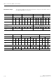


Table Of Contents
- 3 3RT1 contactors/ 3RH1 control relays
- 3.1 Specifications/regulations/approvals
- 3.2 Device description
- 3.3 Application and areas of use
- 3.3.1 3RT10 contactors with 3 main contacts for switching motors
- 3.3.2 3RT14 contactors with 3 main contacts for switching resistive loads (AC-1)
- 3.3.3 3RT12 Vacuum contactors
- 3.3.4 3RT13 and 3RT15 contactors with 4 main contacts
- 3.3.5 3RT16 capacitor contactors
- 3.3.6 Contactors with an extended operating range
- 3.3.7 3RH1 control relays
- 3.3.8 3RT10 contactor relays for switching motors (interface) and 3RH11 control relays for switching auxiliary circuits
- 3.3.9 3RA13 Contactor combinations for reversing
- 3.3.10 3RT14 Wye-delta combinations

3RT1 contactors/ 3RH1 control relays
SIRIUS System Manual
3-20 GWA 4NEB 430 0999-02 DS 01
Wiring example Contactor combinations with PLC-Control 24 V DC
Fig. 3-3: Wiring example: Contactor combinations with PLC control 24 V DC
Contactor combinations with relay control
Important Note
• The terminals H1 shouldn’t be bridged, otherwise all of the contactors will
close when only one contactor should close.
• The terminals H2 shouldn’t be bridged, otherwise the internal connection
of A1 to H2 can be overloaded in the event of a failure.
Control using relay outputs with a common source
Fig. 3-4: Wiring example: Control using relay outputs with a common source.
Control using electrically isolated/ free floating relay outputs
Fig. 3-5: Wiring example: Control using electrically isolated/ free floating relay outputs
+
-
+
-
+
-
PLC-Output
24 V DC / >30 mA
A1
A2
K1
IN+
IN-
A1
A2
K3
IN+ IN-
A1
A2
K2
IN+
IN-
L1/L+
N/L-
+
-
+
-
+
-
PLC-Output
24 V DC / >30 mA
A1
A2
K1
IN+
IN-
A1
A2
K3
IN+ IN-
A1
A2
K2
IN+
IN-
L1/L+
N/L-
A1
A2
K3
H1 H2
A1
A2
K2
H1 H2
A1
A2
K1
H1 H2
6
7
89
L1/L+
N/L-
SIMOCODE-DP
Local control
using
SIMOCODE-DP
A1
A2
K3
H1 H2
A1
A2
K2
H1 H2
A1
A2
K1
H1 H2
6
7
89
L1/L+
N/L-
SIMOCODE-DP
Local control
using
SIMOCODE-DP
A1
A2
K1
H1 H2
A1
A2
K3
H1 H2
A1
A2
K2
H1 H2
Relay control
L1/L+
N/L-