
User Guide
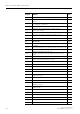
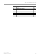


Table Of Contents
- 3 3RT1 contactors/ 3RH1 control relays
- 3.1 Specifications/regulations/approvals
- 3.2 Device description
- 3.3 Application and areas of use
- 3.3.1 3RT10 contactors with 3 main contacts for switching motors
- 3.3.2 3RT14 contactors with 3 main contacts for switching resistive loads (AC-1)
- 3.3.3 3RT12 Vacuum contactors
- 3.3.4 3RT13 and 3RT15 contactors with 4 main contacts
- 3.3.5 3RT16 capacitor contactors
- 3.3.6 Contactors with an extended operating range
- 3.3.7 3RH1 control relays
- 3.3.8 3RT10 contactor relays for switching motors (interface) and 3RH11 control relays for switching auxiliary circuits
- 3.3.9 3RA13 Contactor combinations for reversing
- 3.3.10 3RT14 Wye-delta combinations

3RT1 contactors/ 3RH1 control relays
SIRIUS System Manual
3-10 GWA 4NEB 430 0999-02 DS 01
IV Auxiliary circuit - Auxiliary circuit (contactor relay)
V Main power circuit - Main power circuit
All the data are power system specifications with 10 % overvoltage in volts [V].
400 V + 10 % corresponds to 415 V + 5 % and 500 V + 10 % corresponds
to 525 V + 5 %.
Attention
In the table, the voltage that can cause electric shock and that must be
safely isolated is critical. If the voltages 400 V and 24 V are to be safely iso-
lated from one another, contactors with safe isolation up to 400 V must be
used between the two points of connection used.
3.1.4 Explanation of terms
Safety extra-low volt-
age
Safety extra-low voltage (SELV) allows circuits with a rated voltage of up to
50 VAC or 120 VDC to be operated ungrounded. The higher voltage is safely
isolated from the SELV circuits.
Safety extra-low voltage helps protect people.
Functional
extra-low voltage
Functional extra-low voltage (FELV) allows circuits with a rated voltage of up
to 50 VAC or 120 VDC to be operated. It does not, however, meet the
requirements of safety extra-low voltage and is therefore subject to addi-
tional conditions. FELV is implemented using a ground terminal.
Functional extra-low voltage helps protect devices (e.g. programmable con-
trollers).
PELV PELV (protective extra-low voltage) has the same requirements as safety
extra-low voltage, except for the fact that the circuit and/or exposed conduc-
tive part is/are grounded (so it is basically grounded SELV).
S00
Basic unit - contact
block
690 V* *4-auxiliary contact block
Basic unit 400 V
Contact block 400 V
S00 S0 S2 S3 S6 to S12
400V 400V 400V 400V 400V