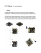
25/10/2016 PIKO BLX FC MANUAL I. ABOUT Designed for micro and mini acro or FPV racers (sub 130 size), this board provides the mostneeded features in a compact and practical form factor. The 27x27mm board has 20mm mounting hole spacing. The board includes power distribution support (up to hex), and a built-in LC filter for FPV video.
II. FEATURES 1. 27x27mm board with 20mm mounting M3 holes. 2. 2.6g with high-quality gold plated 4-layer printed circuit board. 3. Next-generation STM32 F3 processor with hardware floating point unit for efficient flight calculations and faster ARM-Cortex M4 core. 4. Onboard regulator (BEC) 5V-2A for powering the FC, receiver and servos, camera. Direct connection of up to 5s LiPo. 5. PDB build-in with support to Hex for SUB-130 size for very clean and easy setup (size > 130 requires external PDB). 6.
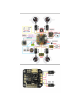
V. QUICK CONECTION 1. Receiver Configurations i. Spektrum Satellite: The onboard JST connector is connected to a 3.3V voltage regulator and uses UART3. ii. SBus: Solder the jumper to SBUS and connect your receiver to the PPM pin (5) on the left side and use UART3. iii. PPM: Solder the jumper to PPM and use the PPM pin (5) on the left side. 2.
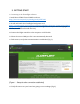
3. GETTING START 1. Connecting to the Cleanflight software. i. Install latest STM32 Virtual COM Port Driver http://www.st.com/web/en/catalog/tools/PF257938 ii. Install and launch the Cleanflight Configurator tool https://chrome.google.com/webstore/detail/cleanflightconfigurator/enacoimjcgeinfnnnp ajinjgmkahmfgb (you need to open this link in Google Chrome. If you don’t have google Chrome, download and install this first) iii. Connect the flight controller to the computer via USB cable. iv.
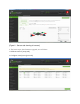
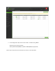
[Figure 2 - Sensors tab showing all sensors] 2. The basic steps, after firmware upgrade, are as follows: i. Calibrate sensors (setup tab) ii.
- UART3 is used for Serial receivers: SBus, SumH, SumD, Spektrum1024/2048, XBus. - UART2 used for Telemetry: Smartport. Cleanflight and Betaflight can send Smartport telemetry to the FrSky X-series receivers over a single wire. Connect UART2_TX port to the S.PORT pin on the receiver. It only takes one wire because the ground connection is already made with the SBUS cable. The voltage divider for LiPo monitoring is built into the Furious FC.
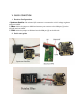
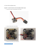
xiii. Tune PIDs during flight testing. Appendix 1 – Quick start with the Furious mini Rx (FRSKy with SBus output) 1. Connect the receiver to the Piko BLX as shown below 2. Connect the SBus pads as shown below 3. Bind the Furious mini Rx to your transmitter https://youtu.
4. Configure the Piko BLX for SBus using the Cleanflight configurator - - In the PORTS tab, select UART3 and activate Serial RX. Save by clicking on the Save and Reboot button. In the CONFIGURATION tab, in the Receiver Mode section, select RX_SERIAL. In the same tab, in the Serial Receiver Provider section, select SBUS. Save by clicking on the Save and Reboot button. Go to CLI and type the following commands: set sbus_inversion = OFF save The FC will reboot, applying the change.
e. In the configuration tab, set the receiver mode – this will be ‘RX_SERIAL’. Now select your receiver provider. Either Spektrum1024 (DSM2) or Spektrum2048 (DSMX) as appropriate That is all you need to set on this tab. Be sure to click on ‘save and reboot’.
f. Satellite binding If you are using a Spektrum DMS2 or DSMX satellite, it is possible to bind the transmitter to the satellite simply while it is connected the flight control, using the CleanFlight configurator. Note: CLI does not work if the board is armed – as always be sure the board is not armed when in this tab. If you are unsure how to do this, please refer to google, or simply bind the satellite using a standard receiver…..
From the configuration tab be sure you have already selected "Rx Serial" and the correct provider (e.g. SPEKTRUM2048 for DSMX) In the CLI tab type "set spektrum_sat_bind = 9" for DSMX or "set spektrum_sat_bind = 5" for DSM2. Type "save" and after the Piko reboots remove the USB cable to power off the Piko. Wait a second and reconnect the USB cable. After cold start satellite led should start blinking and transmitter should be turned on while pressing the bind button.
Double check the channel assignments are correct by moving each stick on your transmitter in turn, and watching for correct slider movement. Control direction check (in the receiver tab): Now that you have the channel assignments correct, carefully check control directions.
Throttle stick BACK (toward you, low throttle) Use your TRANSMITTER servo reverse switches to get the sliders on the screen working in the correct directions. This is what full up elevator, low throttle, left aileron and left rudder should look like. Use your transmitter travel adjust to get the sliders moving from 1000 to 2000 with full deflection on each stick. While on this screen, move the switches on your transmitter, and find one that moves any of the auxiliary functions Aux 1-4.