bintec WI-Client WLAN Ethernet Client Adapter WLAN Serial Client Adapter Manual WI-Client Manual Version 2.
Content: Overview..........................................................................................................................................................3 Technical features:.......................................................................................................................................5 WLAN - Interface:.......................................................................................................................................5 First Time Setup ............
Overview The WI-Client is intended to connect devices with ethernet or serial interfaces to a Wireless Local Area Network (WLAN) corresponding to the 802.11 a/b/g standard. The WI-Client connects over the ethernet interface all devices in its LAN segment with a LAN that is accessible over WLAN. The WI-Client can receive and transmit data over its serial port which are exchanged over LAN or WLAN with other devices, i.e. annother WI-Client or a computer with a suitable software.
The ethernet port has a RJ45 plug. Because of the auto MDI functionality the WI-Client can be attached to a HUB or the LAN port of a computer with standard patch cables. The WI-Client recognizes the cable polarity and automatically connects the right signal lines. The serial port is a 9 pin female D-SUB connector. The pinout makes it possible to connect to a computer COM port with a 1 to 1 serial cable, the exact pinout is shown in Illustration above. The power supply should be 9 – 35VDC / 3W.
Technical features: Processor Type Memory Interface Ethernet Serial 1 Serial 2 Mini-PCI Relay (optional) AUX input (optional) LEDs LEDs Power supply Connector Power consumption Voltage range Circular M8-3pin connector with screw locking < 2.5W (typ.) < 3W (max.) Standard: 8-30V non isolated operating 0 - 70°C ( 32 - 158°F) storage -20 - 80°C ( -4 - 176°F) Board Case Weight 120x100x20mm standard: 125x105x40mm approx.
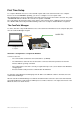
First Time Setup To set up the WI-Client it has to be connected with a patch cable to the ethernet interface of a computer. Because of the auto MDI/MDIX capability, you can use a straight or crossover patch cable. After applying power, the green “Link LED“ on the RJ45 connector shines when a link is detected. The yellow “100 MBit LED“ indicates whether the connection is capable of 100 MBit. The “LAN” LED on the front panel shines green when a connection has been established over the ethernet.
Illustration 4 screenshot of the ComPoint Manager All located WI-Client-Devices are shown in list. A click to a device opens a sub window to change the unit name and the IP address. Reset to factory default The factory default settings can be restored by pressing the reset button located on the front panel for a longer period. After about 5 seconds the LEDs “SER1“ and “SER2“ starts blinking red and green alternately. By keeping the button depressed the factory default values are restored.
Parameter setting via WEB interface Information page General information regarding firmware versions and status reports Illustration 5: Information page On the left hand side are links to different setup and info pages. • • Information the page above(Illustration ) APs Shows a table with all access points currently seen by the WI-Client (Illustration ). • • • Wireless WLAN interface setup (SSID, mode, frequencies etc.
Access Point page Information on all access points currently available to the WI-Client. Illustration 6: Access Point page WI-Client Manual Version 2.
Wireless page Configuring the WLAN interface The WLAN radio can be switch off or here. Wireless mode Infrastructure = Connect to AP Ad hoc = peer to peer connection SSID, Service Set Identifier. Name of the WLAN network. This name must be the same as the access points SSID Transmission rate. Best = automatic depending on signal strength. If useful, you can select a fixed bitrate. The Transmit Power can be adjusted here. 802.11 mode. 802.11b = 2.4GHz 11MBit 802.11g = 2.4GHz 54MBit 802.11b/g = 2.
Security page Setting up the security options If the user selects the 802.1x authentication the PSK or the WEP-Keys don’t have to be defined because the WI-Client and the Radius-Server will determine these parameters automatically. Enable authentication with radius server Select authentication method: EAP-PEAP EAP-TLS EAP-TTLS LEAP (CISCO spec.
Admin page Setting up administration rights and configure basic features, update firmware Reboot the Wi-Client Restore the Wi-Client configuration to default values Select firmware file Upload firmware to Wi-Client Wi-Client Device name: This is a name to identify the WiClient by external configuration and IP address lookup programs, i.e. the locator program. This is not the SSID IP address: By selecting “DHCP” the Wi-Client is assigned the IP address from a DHCP server on the network.
Advanced page The advanced page offers more detailed options to define the behavior of the WI-Client in the WLAN environment. Cloning The cloning parameter defines the MAC address of the WI-Client’s radio. Usually the WI-Client leaves the MAC address at the manufacturers value. All devices connected to the WLAN over the WI-Client’s ethernet port use this MAC address for communication. The WI-Client keeps a table where the original MAC address of the connected device is linked to its IP address.
Roaming Roaming is the term for automatically changing to another access point when the WI-Client recognizes a decreasing RF signal level when leaving the covered area of the current access point and a better level with another AP available. For this purpose the WI-Client keeps a table with a list of access points from which it is receiving signals (beacons). To receive these beacons the WI-Client has to tune to the different channels and listen for incoming signals for a certain amount of time.
Illustration 11: Advanced page WI-Client Manual Version 2.
Serial interface setup The WI-Client can have one or two serial interfaces, depending on the options. Each interface is configured on its own WEB page. Network configuration There are different modes available for the use of the serial interfaces: 1) TCP/IP server mode: In this mode the WI-Client opens a socket in a “listen mode”, which means that it is waiting on a certain port (local port) for a connection. The WI-Client only holds one connection at a time.
Umlenkung. This tool enables the WI-Client to connect to serial devices over LAN/WLAN. After installation of the software enter the WI-Client IP address and port number. Please read and following the license terms of the tool. Comment to the multicast settings In the Multicast-Mode serial busmembers who are communicating with RS485 interfaces can be connected via the (W)LAN. Depending which task the serial device takes it is possible to configure different modes: 1. Slave 2. Master 3.
“Keep alive“ settings A TCP/IP connection remains open after being established until one of the communicating devices closes the connection. If the physical connection between the WI-Client and the other device is interrupted without closing the TCP/IP connection, there is a possibility that the WI-Client is not able to reconnect. The TCP/IP socket can be programmed to send an empty data package to the communication partner in regular intervals (keep alive period).
6) 3964R: This is a special protocol which is commonly used for communication with SPS (programmable control systems). This protocol uses special characters and events to signal when it is ready to transmit and receive. Descriptions of this protocol are available in literature. Illustration 14: Serial interface setup WI-Client Manual Version 2.
Power supply connector The WI-Client is equipped with a circular M8- 3pin connector. The connection is as follows: NC 8-30V M8 cable wire colors: 0V blue 8-30V black NC brown NC = not connected 0V Illustration 15: Power supply connector WI-Client Manual Version 2.
Legal Notice Aim and purpose This document is part of the user manual for the installation and configuration of funkwerk devices. For the latest information and notes on the current software release, please also read our release notes, particularly if you are updating your software to a higher release version. You will find the latest release notes under www.funkwerk-ec.com . Liability This manual has been put together with the greatest possible care.