
User Guide

393231P
Bulletin B1867
902 MHz Wireless Relays Application Manual
Getting Started
• Plan where you will mount each receiver and transmitter.
• Avoid transmitting along a length of wall, sharp angles and large
obstructions.
• Avoid mounting inside a metal enclosure.
• Typical range is 100’ line of sight.
• Link devices to each other before installing. See
linking instructions (per application) on following pages.
• All RIBs must be powered during Link.
page 1
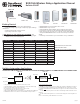
902 MHz Model Power Input (Vac) Contact Rating (A) Transmission Source EEP
RIBW24B-EN3 24 ac/dc 20 Dry-Contact A5-30-02
RIBW01B-EN3 120 20 Dry-Contact A5-30-02
RIBW208B-EN3 208 20 Dry-Contact A5-30-02
RIBW240B-EN3 240 20 Dry-Contact A5-30-02
RIBW277B-EN3 277 20 Dry-Contact A5-30-02
RIBW01C-EN3 120 5 NA A5-30-02
RIBW02C-EN3 208-277 5 NA A5-30-02
WDWS-EN3 None NA Contact Closure D5-00-01
WWS2-EN3 None NA Button Press F6-02-02
WKC-EN3 None NA Insert/Remove Card F6-04-01
WVSCM-EN3 None NA Occupancy Detected A5-07-01
WVSWM-EN3 None NA Occupancy Detected A5-07-01
Compatible Device from other Manufacturers
PHC Gateway Controller EEP A5-38-08
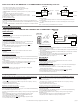
RIBWxxxB-EN3
RIBWxxC-EN3
WDWS-EN3
WWS2-EN3
LRN CLR
WKC-EN3
Functional Devices, Inc.’s EnOcean
®
Manufacturer ID is 0x055.
WVSCM-EN3 WVSWM-EN3
• RIBWxxxB-EN3 is both a transmitter and a receiver.
• RIBWxxC-EN3 is only a receiver.
• Linking a RIB with another RIB puts the pair in Bi-directional mode.
• PHC Gateway Controller can also link with a RIB and be Bi-directional.
• Relay state at power-up can be set to ON, OFF or LAST STATE (default).
(Exception: RIBW24B-EN3 will not save last state when powered from
24Vdc).
• Each Relay can be Linked to up to 30 transmitters of any combination.
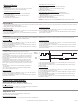
Uni-directional Mode: Only one of the RIBs must transmit. Two RIBWxxxB-EN3 or one RIBWxxxB-EN3 and one RIBWxxC-EN3.
Device Power
Dry Contact
RIBWxxxB-EN3
RIB-1
Device Power
RIBWxxxB-EN3
or RIBWxxC-EN3
RIB-2
Load
Building Automation Applications
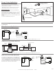
LRN CLR LRN CLR
• Only one RIB is the transmitter while the other is the receiver.
• Transmitter RIB Dry contact closure will transmit a relay ON command; dry
contact open will transmit a relay OFF command.
• Re-transmits dry contact input state every 70-140 seconds.
• Optional modes: Repeater, Alarm (see pages 4)
• When linking a RIB with Version 1.5 firmware (on product label below RIB logo)
to a RIB with an earlier version, the Ver. 1.5 must be RIB-1 in this procedure.
Uni-directional Link Procedure
1. Apply power to both RIB’s.
2. Get RIB-1 in Learn mode by pressing, holding, and releasing the LRN button for approx.
½ second. LED should start blinking. DO not hold LRN button for longer than 2 seconds.
3. On RIB-2 hold LRN button until LED blinks once (approx. 3 seconds) to transmit a Teach
telegram.
a. LED on RIB-1 will stay ON for 4 seconds to acknowledge and then transmit a Teach
telegram.
b. LED on RIB-2 will stay ON for 4 seconds to acknowledge the Teach telegram from
RIB-1.
Note: To clear memory, hold CLR button for 3 seconds.