
User Manual
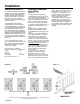
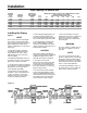

Pipe Capacity For Natural Gas
Nominal Equivalent
Iron Pipe Internal Pipe Length
Size Diameter 90Þ Elbow Tee
Inches Inches Feet Feet 20 40 60 80 100 150 200
1.25 1.38 3.50 6.90 950 — — — — — —
1.50 1.61 4.00 8.00 1460 990 810 — — — —
2.00 2.07 5.20 10.30 2750 1900 1520 1300 1150 950 800
2.50 2.47 6.20 12.30 4350 3000 2400 2050 1850 1500 1280
3.00 3.07 7.70 15.30 7700 5300 4300 3700 3250 2650 22780
4.00 4.03 10.10 20.20 15800 10900 8800 7500 6700 5500 4600
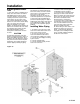
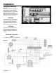
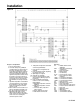
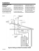
Installing Gas Piping
Figure 4
NOTE
See the above chart for required pipe
size, based on overall Iength of pipe
from meter plus equivalent length of all
fittings. Approximate sizing may be
based on 1,000 BTU for 1 cubic foot of
natural gas.
1. Gas Piping should be installed in
accordance with National Fuel Gas
Code, ANSI Z223 1 1991 or latest
addenda and any other local codes
which may apply.
In Canada gas installations must be in
accordance with the current CAN/CGA
B149.1 and .2 and/or local codes.
2. The pipe and the fittings used should
be new and free of dirt or other deposits
Piping must be of the proper size to
ensure adequate gas supply.
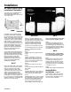
3. Gas pressure to inlet of gas train
should be 7" WC. for natural gas and
11" WC. for propane. Connect gas
supply line to the open end of the tee
on which the drip leg is installed.
4. When making gas piping joints, use
a sealing compound resistant to the
action of liquefied petroleum gases. Do
not use teflon tape on gas line threads.
5. After gas piping is completed and
before wiring installation is started,
carefully check all piping connections,
(factory and field), for gas leaks. Use a
soap and water solution.
CAUTION
Some soaps used for leak testing are
corrosive to certain types of metals. Rinse
all piping thoroughly with clean water
after leak check has been completed.
6. The water heater must be
disconnected at the water heater shut
off valve from the gas supply piping
system during any pressure testing of
the system at pressure in excess of
1
/
2
psig (14" WC)(3.5 kPa).
7.The water heater must be isolated
from the gas supply piping system by
closing its individual manual shut off
valve during any pressure testing of the
gas supply system at test pressures
equal or less than 1/2psi (3.5kPa).
8. Gas vents to outdoor air must be
provided for the pressure regulator and
gas pressure switches. Restricting
orifices or bleed orifices should not be
used at anytime.
WARNING
Do not use matches, candles, flame or
other sources of ignition to check for
gas Ieaks.
NOTE
The vent line connection on the gas
pressure regulator and the low and high
gas pressure switches must be piped
to outdoor air by installer in accordance
with the National Fuel Gas Code, ANSI
Z223- 1-1991 or latest addenda.
In Canada gas installations must be in
accordance with the current CAN/CGA
B149.1 and .2 and/or local codes.
Installation
Figure 4
Maximum Capacity in Cubic Feet of Natural Gas Per Hour
Pressure Drop of 0.5" W.C.
Equivalent Length of Pipe in Feet
13-PDWH
CANADA
US