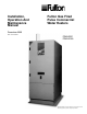
Installation, Operation And Maintenance Manual Fulton Gas Fired Pulse Commercial Water Heaters December 2009 Rev. C June 2011 PDWH750* PDWH1000 *Model PDWH750 is no longer offered but is kept in this manual for reference purposes on previous equipment purchases.
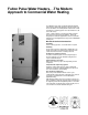
Fulton Pulse Water Heaters. . .The Modern Approach to Commercial Water Heating The application of the pulse combustion principle illustrates how fresh perceptions and changing needs can breathe new life into an old idea. The oldest patents related to this method of burning in a resonating system were issued before the end of the 19th century. Today... advanced pulse technology has finally found and proven its way to the water heater industry.
Contents Section 1 2 3 4 5 Safety Warnings and Precautions-3 Installation-7 Operation-25 Maintenance-33 Parts and Warranty-37 1-PDWH
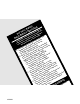
y fet ting a e a S ur Oper w thession o lo , lo r Y ore fol exp age o t o r m F n o a ef do fire rty d life. B u ad : If yoactly, apropess of lot. It is e G R x g lo pi e r IN in a RN tions caus ury o have which A t W ruc ult l inj not evice o no t res na s s in ay rso the doe ition d rner. D d r n ll m pe e u eat n ign he bu and. ll aro sme vier h r o a a t ate with ghts r by h mell a sure t is he w i is ped lly l rne G s Be gas Th A. equip atica the bu ATIN gas. ome or.
Section 1 Safety Warnings and Precautions 3-PDWH
For Your Safety The following WARNINGS, CAUTIONS, and NOTES appear in various sections of this manual. They are repeated on these safety summary pages as an example and for emphasis. WARNINGS must be observed to prevent serious injury, or death to personnel. CAUTIONS must be observed to prevent damage or destruction of equipment or loss of operating effectiveness. NOTES must be observed for essential and effective operating procedures, conditions, and as a statement to be highlighted.
WARNING Do not use matches, candles, flame or other sources of ignition to check for gas leaks. Section 2. NOTE NOTE It is recommended that an authorized Fulton Pulse start up agent make any required gas input adjustments. Section 2. The vent line connection on the gas pressure regulator and the low and high gas pressure switches must be piped to outdoor air by installer in accordance with the National Fuel Gas Code. Section 2.
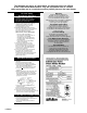
The following are copies of safety labels and warnings which are affixed to the Fulton Pulse Water heaters. They are reproduced here as a further safety precaution and as a reminder to quickly identify them on the water heater. For Your Safety Read Before Operating WARNING: If you not follow these instructions exactly, a fire or explosion may result causing property damage, personal injury or loss of life. A. This water heater does not have a pilot.
Section 2 Installation 7-PDWH
Installation General specifications and information about Fulton Pulse Potable Water Heaters: Models PDWH750 PDWH1000 BTU/HR. Input 750,000 1,000,000 BTU/HR Output* 660,000 880,000 Fuel NG/LPG Approx. Dry Weight 1,800 lbs. Approx. Operating Weight 2,150 lbs. Floor Loading 300 lbs/ft2 Power Required 120/60/1 Min. Required 7" W.C.NG Gas Pressure 11" W.C. LPG Max. Amp Draw (F L.A.) 4.0 MAWP 160 PSI Water heater Width 27.5 IN Water heater Height 76 IN Water heater Depth 37.
Installation Figure 1 *Clearence from top of water heater to combustables must be no less than 12”. AIR INTAKE PIPING Number of Model No. PDWH750 Type PVC PDWH1000 PVC Diameter/In. 4 4 4 4 Length/Ft. 10 Minimum 35 Maximum 10 Minimum 35 Maximum 90 Degree Elbows 0 4 0 4 EXHAUST VENT PIPING Model No. PDWH750 Type Stainless Steel PDWH1000 Stainless Steel Diameter/In. 4 4 4 4 Length/Ft.
Installation Locating The Water Heater: The water heater should be located so that the air supply and exhaust piping between the water heater and outside wall/roof are within the minimum and maximum lengths for horizontal or vertical venting. (Page 9) See Figure 1 for minimum clearances between the water heater and any combustible surfaces. CAUTION Do not install the water heater in an uncontrolled environment where the condensate will be subject to freezing temperatures.
Installation Installing Water Heater Trim 1. Each water heater is supplied with a safety relief valve sized in accordance with ASME requirements.The safety relief valve shall be connected to the coupling located in the top of the water heater (Figure 3a). The safety relief valve must be installed with a 6" nipple between the water heater and the safety valve. The safety relief valve must always be installed in the vertical position.
Installation Condensate Drain Kit The condensate drain kit is intended to be utilized with any size pulse unit supplied by Fulton. The 3/4” condensate drain on the pulse unit will be connected to the 1” inlet on the drain kit. One or more drain lines may be connected to this inlet (maximum of 8 total per drain kit) through a common header. An uninterruptable water supply is required and shall be connected to the 1/4” compression fitting on the drain float.
Installation Pipe Capacity For Natural Gas Nominal Iron Pipe Size Inches Internal Diameter Inches 1.25 1.50 2.00 2.50 3.00 4.00 1.38 1.61 2.07 2.47 3.07 4.03 Equivalent Pipe Length 90Þ Elbow Feet 3.50 4.00 5.20 6.20 7.70 10.10 Installing Gas Piping Figure 4 NOTE See the above chart for required pipe size, based on overall Iength of pipe from meter plus equivalent length of all fittings. Approximate sizing may be based on 1,000 BTU for 1 cubic foot of natural gas. 1.
Installation Installing Field Wiring Figure 5 It is recommended that an independent power supply line be provided for the water heater. Connect one 120 volt (60Hz) fused powerline to terminal block as shown in Figure 5a. Connect applicable wires to neutral and ground. Connect a ground wire to green colored ground lug in electrical control box. WARNING Do not attempt to start water heater to test wiring before filling and purging the water heater.
Installation Figure 5b Sequence of Operation 1. Turn on main breaker. 2. Low water safety relay (LWSR) is energized when the main breaker is turned on. (Red light on the water heater panel is lit and if the optional alarm is provided, alarm will go off. Current is not allowed to pass to the high limit temperature control until a) the probe in the water heater shell senses the water and b) the manual reset switch is reset. If a and b are both satisfied, the red light is turned off. 3.
Installation Air Intake Supply Piping Installation Preparation The water heater is equipped with air intake supply and exhaust vent connections located at the top and rear of the water heater. Air Intake Water Heater Connection Schedule 40 PVC Pipe Pipe-to-Tubing Adapter Figure 6 Air supply is on the top. See Figure 6. For Models PDWH750 & PDWH1000, the connections are 4" NPT thread female fittings. These fittings will accept 3" and 4" male/female pipe to tubing adaptors respectively.
Installation Exhaust Vent Piping Installation Preparation NOTE: A Fulton PDWH water heater should not be connected to a common venting system with other types of gas appliances. The water heater is equipped with an exhaust vent connection located at the rear of the water heater. (Figure 6) For Models PDWH750 & PDWH1000 the connections are 4" NPT threaded female fittings. The exhaust line must be sloped down toward the unit with a pitch of at least 1/4" per foot.
Installation Air Intake Supply and Exhaust Vent Installation Air intake supply and exhaust vent pipes and fittings are suitable for vertical, through-the-roof or horizontal through-the-wall installation. The vent system must be installed in accordance with the manufacturer’s instructions. All vent pipes and fittings must be installed with appropriate air space clearances to combustibles.
Installation Figure 9 Fire Stopping Required For All Ceiling/Floor Penetrations Figure 10 Fire Stop Figure 11 Elements For Correct Roof Flashing Installation Nail through the upper portion and sides of the base flange. Use nail with neoprene washers or cover the nail heads with a neoprene plastic. through the four holes in the ring. The fire stop is placed on top of a framed opening 141/4" square with the dished position down. Nail the flange to the top of the framing.
Installation Horizontal Installation Wall Penetrations Figure 13 Select the point of penetration where a minimum of 1/4" per foot upward pitch can be maintained. Figure 13 20-PDWH When penetrating a non-combustible wall, the hole through the wall must be large enough to maintain the pitch of the vent and provide sealing. Use adhesive material to seal around the vent on both sides of the wall. When penetrating a combustible wall, a wall thimble must be used.
Installation Figure 14 Nominal Pipe & Thimble Diameters Pipe Size (in.) A Ø BØ CØ 7 7 3" 6 /8" 5 /16" 35/16" 4" 93/8" 81/2" 43/16" 1 6" 8 /8" Fixed 61/8" Pipe Size (cm) A Ø BØ CØ 7.62 17.46 13.81 8.41 10.16 23.81 21.59 10.63 15.24 20.64 Fixed 15.56 Wall Thimble Installation Horizontal Vent Termination A 9" diameter thimble is inserted through the wall from the outside. Secure the outside flange to the wall with nails or screws, and seal with adhesive material.
Installation to vent these locations. When only water is discharged from all vents, the initial purging is complete. WARNING Never leave an opened manual air vent unattended. In the event an opened vent is left unattended, water damage could occur. f. Visually inspect all pipe joints and equipment connections for leaks. If necessary, drain system, repair leaks and refill/purge the system. If no pressure drop is detected for a period of two hours under pressure, the system may be considered water tight. g.
Installation Installation Guidelines Pipe Material: Fulton recommends stainless steel (300 or 400 series), galvanized steel, or copper piping for potable water systems incorporating a PDWH. Local code requirements may also dictate feasible materials. Water Quality: Failure to maintain appropriate water chemistry and quality will void the factory warranty on the heater. Water must be treated if it is not in compliance with the guidelines below.
Installation Installation Checkpoints 1. Before Starting The Water Heater: Do not turn on the water heater unless it is filled with water as shown by indicating light on panel box. 2. Check that the front door of the air decoupler box is closed. Door must be closed before starting the water heater. DO NOT OPEN DURING OPERATION. 3. Adjust temperature to proper setpoint.
Installation Pressure for Natural gas should measure 1 to 3" WC at the last elbow on the gas train at high fire, or full rate on on/off units. For more specific information, consult the test fire report which is included in the User Manual. There should be 7" WC at the inlet of the train. Pressure for propane should be 11" WC at inlet to the gas train. To Correct Input—Adjust Gas Pressure Regulator Figure 16 Figure 16. Replace the plug with a 1/4 N.P.T.
- PAGE INTENTIONALLY LEFT BLANK -
Section 3 Operation 26-PDWH
Operation Post these instructions in an appropriate place near the water heater and maintain in good legible condition. 1.Set the water temperature to desired setting. NOTE WARNING Prior to starting, make sure the procedure for purging the system has been accomplished as detailed in Section 2. If you do not follow these instructions exactly, a fire or explosion may result causing property damage, personal injury, or loss of life. Fulton Pulse water heaters do not have a pilot.
Operation Causes for hold conditions in the INITIATE sequence are: DO NOT CHANGE THE PRESSURE SWITCH SETTINGS. Check for possible restrictions (foreign objects, snow, rags, leaves, etc.) in either the air supply inlet or the exhaust outlet on the outside of the building. Check reset switch. Check for proper water level in the water heater (low water cutoff). If the water heater still does not operate, follow these instructions to shut off the gas and call your service technician.
Operation IGNITION TRIALS (Without Flame Rod Option) a. Combustion Pressure Establishing Period (CPEP): 1. The ignition transformer, terminal 10, is energized two seconds prior to opening of the main fuel valve. 2. The main fuel valve, terminal 8. is energized for four seconds. Combustion pressure must be proven by the end of the six seconds of CPEP to allow the sequence to continue to the Combustion Pressure Stabilization. Period (CPSP).
Operation Sequence of Operation for Modulated Pulse Water Heaters adjusted according to system design. Once the desired value is displayed, press the SET/ENT key to maintain it in the control’s memory. 1. When the water heater receives a call for heat, the prepurge cycle is initiated. Only those values that are Shaded with Bold & Italic values in the menu pertain to the program constructed for Fulton pulse water heaters. 2. The mod motor is driven to high fire. 3.
Operation Worksheets for Yokogawa UT320/UT350 Temperature Control Program for Pulse Modulating Water Heaters Input/Output Menu SYMBOL IN UNIT RH RL SDP SH SL RJC BSL OT RET RTH RTL DIS C.S1 C.S2 C.S3 C.
Operation Operating Parameters SYMBOL AL1 AL2 AL3 AT SC SP.no Pld FL BS UPR DNR OH OL H DR HB1 HB2 HC1 HC2 ORB ORH ORL OR 1.SP 2.SP 3.SP 4.
Operation Linkage Adjustment for Pulse Modulated Water Heaters This instruction covers the adjustment of the linkage arms and rods between the modulation (mod) motor and gas butterfly valve and also between the mod motor and exhaust butterfly valve. Prior to Start-Up - With the water heater off, both the gas and exhaust butterfly valves will be in the closed position.
Section 4 Maintenance 34-PDWH
Maintenance NOTE Your Fulton Pulse water heater has been designed for years of trouble-free performance. To ensure the continued safety and efficiency of the water heater, the schedule of maintenance outlined in this section should be adhered to. The water heater should be inspected annually. All service should be performed by a certified contractor. Recommended Monthly Maintenance Recommended Annual Maintenance Inspect the air intake and exhaust vent pipes for broken seals at the joints.
Maintenance Troubleshooting This troubleshooting guide will assist in the diagnosis and correction of minor field problems. It should be used in conjunction with the unit wiring diagram. In any case requiring additional assistance, the Fulton Service Department should be contacted. Problem Cause Check Starting or Purge Failure Power Supply Check fuse or circuit breaker. Reset or replace, as necessary. On/Off Switch For all models check to see if on/off switch is illuminated.
Maintenance Troubleshooting--Fault Code Diagnosis Fault Code System Failure Recommended Troubleshooting Fault 02 *AC Frequen/Noise* Excess noise or device running on slow AC. 1. Check the relay module and display module connections. 2. Reset and sequence the 7800. 3. Check the 7800 power supply to assure that both frequency and voltage meet specifications. 4. Check the backup power supply as appropriate. Fault 03 *AC Line Dropout* AC Line dropout detected. 1.
Section 5 Parts and Warranty 38-PDWH
- PAGE INTENTIONALLY LEFT BLANK -
Replacement Parts Part Number (available from authorized Fulton Representatives) Description 2-30-000232 Air switch-purge fan 2-30-001334 Air switch-proof of flame 2-12-000551 Air flapper gaskets Air Flapper Spacers and Valve Assemblies* 7-37-000124 Air flapper valve assy w/o housing 7-37-000123 Air flapper valve assy w/o housing 2-40-000251 Aquastat-operating temp. 2-40-000250 Aquastat-high limit-m/r 2-40-000220 Gas valve actuator w/P.O.C.
Replacement Parts Part Number (available from authorized Fulton Representatives) Description Models PDWH 750 1000 Accessories 2-45-000212 5-60-000130 4-57-000440 2-10-000168 2-35-000863 2-35-000865 2-35-000611 2-35-000861 2-35-000862 2-35-000531 2-35-000532 2-30-000498 2-45-000040 2-23-000170 4-23-000016 2-35-000799 5-10-002765 5-10-002755 2-35-000059 4-57-000168 4-57-000164 4-57-000170 H-O-A Switch Instruction Manual Condensate drain kit Condensate drain float assembly Isolation cube Isolation spring-
Replacement Parts Part Number 2-35-000987 2-35-000812 2-35-000571 2-35-000810 2-35-000583 2-35-000983 2-35-000980 2-35-000981 2-35-000582 2-35-000573 2-35-000982 2-35-000574 2-35-000575 2-35-000576 2-35-000577 2-35-000962 2-35-000960 2-35-000985 2-35-000572 2-35-000984 2-35-000961 2-35-000813 2-35-000986 2-35-000971 2-35-000811 2-35-000972 2-35-000973 2-35-000974 2-35-000975 2-35-000976 2-35-000977 2-35-000991 2-35-000992 2-35-000993 2-35-000994 2-35-000995 2-35-000997 2-35-000998 2-35-000996 2-60-000114 2-
- PAGE INTENTIONALLY LEFT BLANK - 42-PDWH
Warranty Standard Warranty for Fulton Pulse Domestic Boilers Warranty Valid for Models PDWH Ten (10) Year Thermal Shock Warranty Fulton Heating Solutions guarantees the Pulse hot water pressure vessel against thermal shock for a period of ten (10) years when the boiler is installed and is operated per the Installation and Operation Manual. This guarantee will cover damage due to thermal shock, such as leaks in the heat exchanger.
- PAGE INTENTIONALLY LEFT BLANK -
- PAGE INTENTIONALLY LEFT BLANK -
No part of this Installation, Operation, and Maintenance manual may be reproduced in any form or by any means without permission in writing from Fulton Heating Solutions, Inc. For more of the following patents apply to this unit: U.S. Patent Numbers 4856558, 4884963, 4926789, 4951706 and 5, 145, 345. Swiss Registration Numbers 119122 and 119243. SwdeishRegistration Numbers 51873 and 51874. German Patent Number M9104923.7. Benelux Registration Numbers 21548-01/02, 03/04 and 21548-05/06.