Serial Number: _______________________________ Model Number: _______________________________ Instruction, Operation, and Maintenance Manual Fulton Order Number: _______________________________ Sold To: _______________________________ Fulton Oil Fired Steam Boilers Job Name: _______________________________ Date: _______________________________ 4 HP to 60 HP
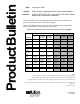
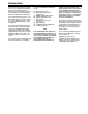
ProductBulletin Date: January 22, 2010 Subject: Water Chemistry Requirements for Fulton Steam Products Products: ICS/ICX, FB-A, FB-F, FB-S, VMP, PVLP, PHP, Electric Steam Boilers and Unfired Steam Generators Please note that the water chemistry is different for carbon steel vs. stainless steel pressure vessels and vertical vs. horizontal orientation. Effective immediately, please use the limits below. Should you have any questions, please do not hesitate to contact Fulton at 315-298-5121.
Introduction This manual is provided as a guide to the correct operation and maintenance of your Fulton Oil Fired Steam Boiler, and should be permanently available to the staff responsible for the operation of the boiler. These instructions must not be considered as a complete code of practice, nor should they replace existing codes or standards which may be applicable. The requirements and instructions contained in this section generally relate to the standard Fulton Oil Fired Steam Boiler.
Contents Section 1 2 Safety Warnings & Precautions 3 Operation 4 Maintenance 5 Parts 6 7 Warranty 1-O 4/00 Description/Instructions Specifications & Dimensions 4-60 HP Locating the Boiler The Fuel Oil Supply Boiler, Condensate Tank, and Blow off Separator Piping Boiler Installation The Steam Supply The Steam Safety Valve The Steam Pressure Gauge Assembly The Blow Off Valve The Feed Water Piping Water Gauge & Gauge Glass Installation Instructions The Water Column Water Supply Recommended Water Tr
Safety Warnings/Precautions 1 2-O 4/00
Safety Warnings/Precautions Safety Warnings, Cautions & Notes The following WARNINGS , CAUTIONS, and NOTES appear in various chapters of this manual. They are repeated on these safety summary pages as an example and for emphasis. WARNINGS must be observed to prevent serious injury, or death to personnel. CAUTIONS must be observed to prevent damage or destruction of equipment or loss of operating effectiveness.
Boiler Description/Instructions Oil Fired Boiler 2 4-O 4/00
Description/Instructions Magnetic Oil Valve Oil Pump Transformer Scroll Burner Motor Burner Plate Assembly Secondary Air Damper Top Plate Assembly ;;;;;;;;;;;;;;;;;;; * QQQQQQQQQQQQQQQQQQQ ;;;;;;;;;;;;;;;;;;; QQQQQQQQQQQQQQQQQQQ ;;;;;;;;;;;;;;;;;;; QQQQQQQQQQQQQQQQQQQ ;;;;;;;;;;;;;;;;;;; QQQQQQQQQQQQQQQQQQQ ;;;;;;;;;;;;;;;;;;; QQQQQQQQQQQQQQQQQQQ ;;;;;;;;;;;;;;;;;;; QQQQQQQQQQQQQQQQQQQ
Fulton Models: ICS/FB-A and ICX/FB-F Fulton Gas & Oil Fired Vertical Tubeless Steam Boilers Dimensions (Standard Burner) Product Data Submittal Standard Models ICS/FB-A Models ICX/FB-F Unit Size: BHP A. Boiler Height IN MM B. Boiler Height With Trim* IN & Fuel Train Assembly MM C. Overall Depth Stack IN to Burner Fan Housing MM D. Boiler Diameter IN MM E. Overall Width IN with Water Column MM F. Flue Outlet Diameter IN MM G. To Center of Flue Outlet IN MM H. Feedwater Inlet IN MM I. Handholes IN MM J.
Specifications Models ICS/ICX/FB Boiler Connections N. Steam Outlet 15 PSI N. Steam Outlet 150 PSI O. Safety Valve Outlet 15 PSI O. Safety Valve Outlet 150 PSI+ (9.5 HP 100 PSI) P. Safety Valve Inlet 15 PSI++ P. Safety Valve Inlet 150 PSI (9.5 HP 100 PSI) Q. Feedwater Inlet R. Blowdown Outlet S. Water Column Blowdown IN MM IN MM IN MM IN MM IN MM IN MM IN MM 4 6 9.5 10 1” 25 1” NPT N/A 1.5” NPT 0.75” 19 0.75” NPT 1” NPT 0.75 19 1 25 0.75 19 0.75 19 0.75 19 1 25 1 25 0.75 19 1 25 0.75 19 0.
Description/Instructions K K I F E J K D C H B A G 7-O 4/00
Description/Instructions PLEASE SEE DATA SHEETS ON PREVIOUS PAGES Locating the Boiler a) The boiler should be located in dry surroundings on a level base, making sure that there is sufficient room around the boiler to enable the operator and/or the maintenance engineer to gain access to all parts of the boiler. Check location for ease of water supply and electrical connections.
Description/Instructions Basic Boiler, Condensate Tank, and Blow off Separator Note Where a condensate return tank is to be fitted, this should: 4) Return pipes must not be insulated. This can cause overheating the return system, causing a vapor lock in the pump. 1) Be vented and 5) See Return System Instruction Manual for detailed instructions. 2) Have a capacity sufficient to satisfy boiler consumption as well as maintain proper return tank temperature.
Description/Instructions Warning Blow down and return system vents and drains must be piped in accordance with local codes. Failure to do so could result in severe personal injury. a) Make sure two check valves are installed between the boiler and pump (one check valve is supplied with the unit). b) In a closed system an end of the line trap should be installed. c) There are two blow off valves on the boiler; the main valve at the rear of the boiler and the water gauge glass blow off valve.
Description/Instructions Boiler Installation The Steam Supply — Pipe the steam supply line from the top right side of the boiler. Steam Pressure Gauge The Steam Safety Valve 1) Before installing, be sure that all pipes and connections have been blown clean. Pipe compound or dope is used on external threads only. Be sure inlet of valve is free of any foreign material.
Description/Instructions The Blow-Off Valve— There are two blow off valves on the boiler; the main valve at the rear of the boiler and the water gauge glass blow off valve. The boiler blow off valve supplied with the boiler should be screwed to the blow off pipe at the rear of the boiler and connected to a blow off receptacle of approved design. This should be done in accordance with state and local codes. 4) Do not use the pump as a piping support.
Description/Instructions Water Gauge & Gauge Glass Installation instructions Note Only properly trained personnel should install and maintain water gauge glass and connections. Wear safety glasses during installation. Before installing, make sure all parts are free of chips and debris. Note Keep gauge glass in original packaging until ready to install. Warning 9) Carefully slide upper glass packing up as far as possible. 10) Hand tighten both glass packing nuts, then tighten 1/2 turn more by wrench.
Description/Instructions Water Supply Boiler Water: a) Feed water contains solids and dissolved gases. These may promote incrustation of scale; foaming, priming, surging, and solids in steam; corrosion and pitting; or caustic embrittlement. To prevent this, feedwater must be studied individually and treated accordingly by reputable professionals specializing in this field. It is strongly recommended that a competent water treatment company be consulted prior to the installation of the boiler. Phosphate .
Description/Instructions Both foaming and carry over cause erratic boiler operation. When foaming occurs an anti-foam should be added or increased. The reason for the high alkalinity should be determined. It may result from lack of sufficient blow off. Pretreated makeup water and condensate should also be checked. Quite often the source of alkalinity is an overdose of alkaline internal water treatment chemical.
Description/Instructions Electrical Requirements a) Connect wiring as shown in the wiring diagram which is furnished inside the electrical control panel box. b) Be sure to install a fused disconnect for the blower and/or pump.. The disconnect should be installed in compliance with the NEC (National Electric Code) and all local codes. c) Connections for an optional audible alarm are provided in the control panel and are clearly indicated on the diagram.
Description/Instructions Conventional Venting a) The stack should rise continuously to the connection with the chimney, and should contain no more than two bends at 45 angles or less. If required as the result of space limitations, one 90 elbow can be fitted at the back of the boiler. There should be two feet of straight, horizontal flue before any bends or turns. Any alternative stack arrangement must supply -.02 -.04” W.C. pressure (-0.508 to -1.016 mm) with the burner off.
Description/Instructions Exhaust Side Wall Venting (UL and MEA Approved- MEA File Number 68-79-E Vol. 2 ) 5) The draft fan shall have an air flow proving switch wired in series with the boiler air safety switch. a) Boilers for which sidewall venting may be utilized are No. 2 oil, natural gas, or combination No. 2 oil and natural gas,sizes 4 to 30 H.P.
Description/Instructions Installation Check Points 1) Make sure all piping connections are complete and tight. 3) Mix washing soda with water in a one-gallon container and pour it into the boiler through the steam safety valve opening. 7) Generate 15 PSI (1.054 kg/cm2) of steam and shut off the boiler. Allow this hot solution to remain in the boiler for 10 minutes. 2) Make sure the pressure controls are adjusted properly.
Operation 3 20-O 4/00
Operation Starting the Oil Fired Boiler 3. Open main steam stop valve at the top of the boiler. Stop! Make sure you have read any followed all previous safety information. a) The fused disconnect switch that controls the feed water pump should be kept in the "on" position at all times during the boiler operation as well as during the non-operating period of the boiler. Check with local authorities where approval for start-up is required. In some localities, final inspection of services may be required.
Operation Oil Burner Set Up a) Open the oil line shut off valves. b) Switch on the main power to the burner. Depress the manual reset button on the panel box. c) To start the burner, turn on the switch located on the panel box. The blower motor will now start to deliver the air into the furnace. As the blower starts, the magnetic oil valve is energized allowing the oil pump to deliver fuel to the furnace where it is ignited. d) On Fulton 4-15 h.p.
Operation Primary Air Adjustment Procedure a) The primary air adjustment or main air control is located at the fan housing face. This control is used to supply the burner with excess air to facilitate good combustion. Too much or too little air will result in poor combustion. It is important to make sure the lowest level of excess oxygen is present while still maintaining a high level of carbon dioxide and negligible carbon monoxide.
Operation Boiler Controls a) Flame Safeguard/Burner Control – this is the main control in the panel box. The programmer in conjunction with a sensing device, either a cad cell (4-15 h.p.)or an ultra violet scanner (20-60 h.p.), "supervises" the iginition sequence proves the flame is satisfactory and finally "monitors" the established flame. Should any fault occur, either during the ignition sequence or during normal running, the programmer will immediately go to "lock-out" and the burner will shut down.
Maintenance 4 25-O 4/00
26-O 4/00
Maintenance Magnetic Oil Valve Oil Pump Transformer Scroll Burner Motor Burner Plate Assembly Secondary Air Damper Top Plate Assembly ;;;;;;;;;;;;;;;;;;; * QQQQQQQQQQQQQQQQQQQ ;;;;;;;;;;;;;;;;;;; QQQQQQQQQQQQQQQQQQQ ;;;;;;;;;;;;;;;;;;; QQQQQQQQQQQQQQQQQQQ ;;;;;;;;;;;;;;;;;;; QQQQQQQQQQQQQQQQQQQ ;;;;;;;;;;;;;;;;;;; QQQQQQQQQQQQQQQQQQQ ;;;;;;;;;;;;;;;;;;; QQQQQQQQQQQQQQQQQQQ ;;;;;;;;;;
Maintenance Procedure for Cleaning Water Probes - (Recommended as Annual Maintenance) Clean probe on top of boiler shell and probes in water column. Make sure there is no pressure on the boiler during the removal of the probes. Remove one probe, clean with very fine emory cloth and replace it before removing another to assure no probe mix ups that would change the control functions. For replacement purposes, installed probe lengths are indicated in the chart below.
Maintenance Cad Cell (4–15 HP) Scanner Location (20–60 HP) Primary Air Gate Oil Inlet Electrodes Burner Plate Observation Port Secondary Air Gate Top Plate Blast Tube Air Deflector Flame Signal Detection for Fulton Oil Fired Steam Boilers a) It is essential to obtain optimum flame signal detection for safe and continual operation of the combustion control relay.
Maintenance Furnace Refractory Replacement Procedure a) Remove the burner plate and top plate assembly up and out of the scroll assembly. b) Remove the stainless steel combustion ring from the furnace. c) Remove the clean-out plugs from the bottom sides of the boiler. 4-15 HP boilers have one cleanout plug located at the bottom of the boiler directly below the panel box. 20-60 HP boilers have one cleanout plug located at the bottom of the boiler to the right side of the panel box.
Maintenance Recommended Daily Maintenance Schedule Recommended Monthly Maintenance Schedule a) The following procedures should be carried out daily. They are designed to prevent the build up of scale, silt, or sludge in the bottom of the boiler and in the pipes leading to the water gauge. In addition to these procedures, the advice of a water treatment supplier should be sought and followed. An ASME Section VIII blow off receptacle must be provided for the appropriate pressure.
Maintenance g) Remove pipe plug at the cross connection below water column and clean nipple into boiler. Boiler must be cold and water level below pipe. 1-3/4" (44.5 mm) 1-3/4" (44.5 mm) 7/8" (22.2 mm) Remove cap at cross section; clean nipple to boiler 7/8" (22.2 mm) 9/16" (14.3 mm) 2-3/8" (60.3 mm) (Nom) 9-1/4" (228.6 mm) – 4 HP 11-3/8" (288.9 mm) – 6-30 HP 10-3/4" (273 mm) – 40-100 HP Recommended SemiAnnual Maintenance Schedule a) Clean the oil burner assembly1) Clean fan blades; oil the motor.
Maintenance g) Replace handhole gaskets using the following procedure: 1) Remove the handhole assembly using a 1-1/4" tee handle wrench or 1-1/4" socket wrench. prevent leakage. Excessive tightening may shorten the life of the gasket. Illustration shows over compressed gasket Removing handhole assembly with a Tee Handle Wrench 2) Remove the old gasket and thoroughly clean the surface on the boiler and the plate.
Maintenance Troubleshooting a) The following trouble shooting guide will assist in the diagnosis and the correction of minor field problems. It contains instructions and information necessary to locate and isolate possible troubles which occur during normal operation. It should be used in conjunction with the unit wiring diagram and the component literature provided in Section 7 of this manual. b) The following lists cover the most common troubles that may occur on the Fulton oil fired boilers.
Maintenance Problem Cause Remedy Flame Failure 4. Oil Valve Check voltage between oil valve lead neutral at terminal block to be sure oil valve is getting power. 5. Oil Pump Check for clogged strainer or filter. Remove and clean. Check for slipping or broken coupling.Ttighten or replace. Check for frozen pump shaft. Replace. 6. Loss of Oil Prime Check all lines for possible air leak in intake line and tighten. Check for possible restricted intake line. Replace. 1.
Maintenance Problem Cause Remedy Burner Cut-Off (cont.) 10. Dirty Scanner/Cad Cell Check scanner/cad cell and clean as necessary. 11. Low Water Cut Off Relay failure Make sure relay is plugged in tightly. If so, and still inoperative, replace. 1. Refractories Check refractories to see if they are plugged with soot or broken in pieces. Clean or replace as necessary. 2. S.S. Ring Check to be sure ring is present and fits tight against the furnace wall. 3. Oil Nozzle Check for clogged nozzle.
Maintenance Problem Cause Remedy Burner backfires (cont.) 8. Loose Oil Fittings Check all fittings and tighten. 9. Plugged Oil Filter Check and clean or replace. 10. Plugged screen in oil pump Check and clean or replace. 11. Plugged Flue Check flue to see if it is plugged. Check draft at flue. Clean. 12. Vacuum on pump Check for too high a vacuum on the pump. Check oil lines and distance from tank to boiler. Repair or replace as necessary. 13.
Maintenance Problem Cause Boiler is Surging (cont.) 4. Too much compound in Dump return tank and flush system. Have water tested by system (water treatment) water treatment company. Boiler Rumbles and Pulsates Boiler pushing water with the steam Pump will not cut off Pump runs but does not put water into boiler Remedy 5. Too much water softener (high PH) Have water tested by water treatment company. 6.
Maintenance Problem Cause Water pump will not come 1. Scale on Probes on at times 2. Bad Pump Contactor 3. Bad Pump Motor Remedy Check and clean or replace as necessary. Check to see if contactor is being powered. Check to see if contactor coil is pulling in. Replace if necessary. Check the incoming power to the pump to be sure it is receiving power. If power is present but motor does not run, replace it. Boiler has after burn when 1.
Parts 5 40-O 4/00
Parts Spare Parts a) It is important that the correct replacement part is fitted to your Fulton Oil Fired Steam Boiler. b) When ordering replacement or spare parts, make sure that the full information given in the Parts List is supplied, together with the following details as shown on your boiler identification plate: 1. Boiler Number 2. Boiler Type 3. Electrical Specifications Note: The policy of Fulton Boiler Works, Inc.
Parts Replacement Parts Listing (available from authorized Fulton Representative) Part No. Description 5-60-100 5-60-165 5-60-164 Instruction Manual, Fuel-Fired Certification Papers Boiler Documentation for Export Boilers 5-12-005 5-12-007 5-12-008 5-12-009 5-12-010 5-12-011 5-12-012 5-12-015 5-12-016 Approx. Approx. Net Weight Net Weight (lbs.) (kgs.) 2 0.
Parts Part No. Description Approx. Approx. Net Weight Net Weight (lbs.) (kgs.) 5-21-300 5-21-301 5-21-302 5-21-303 5-21-304 5-21-305 5-21-306 Steel Jacket 4 HP - No Holes Cut Steel Jacket 6 HP - No Holes Cut Steel Jacket 10 HP - No Holes Cut Steel Jacket 15 HP - No Holes Cut Steel Jacket 20 HP - No Holes Cut Steel Jacket 30 HP - No Holes Cut Steel Jacket 40-60 HP - No Holes Cut 80 80 100 115 125 125 125 36.36 36.36 45.45 52.27 56.82 56.82 56.
Parts Part No. Description 2-23-171 4-23-014 4-23-044 2-12-504 Touch Up Paint - MICA Spray Mica Paint - Quart Mica Paint - Gallon TIW Filler Insulation per sq ft 2-40-605 2-40-606 2-40-603 2-40-770 Approx. Approx. Net Weight Net Weight (lbs.) (kgs.) 1 2 7.8 0.45 0.91 3.55 Burner Assembly - Parts (Common 1/3 HP 115/230/60/1 Burner Motor 3450 RPM 1/3 HP 230/460/60/3 Burner Motor 3450 RPM 1/3 HP 110/220/50/1 Burner MOtor 2850 RPM 1/3 HP 380/50/3 Burner Motor 2850 RPM 21 20 25 28 9.55 9.09 11.36 12.
Parts Part No. Approx. Approx. Net Weight Net Weight (lbs.) (kgs.
Parts Part No. Description Approx. Approx. Net Weight Net Weight (lbs.) (kgs.) 2-40-221 2-40-222 2-20-007 Cad Cell with Holder Cad Cell Only Cad Cell Adaptor 0.1 0.1 0.4 0.05 0.05 0.18 2-30-130 2-30-129 2-30-049 2-30-050 2-30-052 2-30-054 2-30-056 2-30-057 2-30-058 Magnetic Oil Valve 115V Magnetic Oil Valve 230V Oil Nozzle 1.35 GPH - 80° 4 HP Oil Nozzle 1.65 GPH - 80° 6 HP Oil Nozzle 2.25 GPH - 80° 10 HP Oil Nozzle 3.50 GPH - 80° 15 HP (one) and 30 HP (two) Oil Nozzle 5.
Parts Part No. Description Approx. Approx. Net Weight Net Weight (lbs.) (kgs.) 5-20-022 2-30-151 2-30-193 2-30-152 2-30-192 2-12-125 2-30-136 2-30-137 2-45-144 2-45-143 Water Column Fulton Water Column Bottle Casting -4-60 HP MM 150 Pump Control MM 150 - M/R Control MM 150 HD Assembly MM 150-M-HD M/R Head MM 150-14 Gasket MM 157 Pump Control and Low Water Cutoff MM 53-2 Boiler Feeder and Low Water Cutoff MM Mercury Switch - 2 Wire MM Mercury Switch - 3 Wire 20 25 25 25 25 0.05 39.7 38.5 1 1 9.09 11.
Parts Part No. Description 2-12-090 Spring Retainer for burner/pump relay 2-40-403 2-40-402 2-40-400 2-40-401 4-45-050 4-45-051 2-40-131 2-40-096 Approx. Approx. Net Weight Net Weight (lbs.) (kgs.) 0.001 0 IDlDO - 120V Relay IGIDO - 120V Relay IGlDO-A-120V Relay ID2DO - 220V Relay Set of three (3) Coils for ID or IG Type Relay Set of three (3) Coils ID2D0 - 220V General Purpose Relay (Ice Cube) - AB Base for Ice Cube Relay 2 2 2 2 1 1 0.8 0.1 0.91 0.91 0.91 0.91 0.45 0.45 0.36 0.
Parts Part No. Description Approx. Approx. Net Weight Net Weight (lbs.) (kgs.) 2-40-201 2-40-203 Motor Starter Relay - 220V - 20 AMP Motor Starter Relay - 220V - 30 AMP 0.4 0.5 0.18 0.23 2-40-223 2-40-224 8184 Protectorelay - Oil - 120V 8184 Protectorelay - Oil - 220V 3.25 3.25 1.48 1.
Parts Part No. Description Approx. Approx. Net Weight Net Weight (lbs.) (kgs.) 2-30-391 2-30-392 2-30-393 1" Y Type Blowdown Valve - 200# 1-1/4" Y Type Blowdown Valve - 200# 1-1/2" Y Type Blowdown Valve - 200# 4 5.5 8.4 1.82 2.5 3.82 2-30-007 2-30-014 2-30-023 1" Quick Action Blowdown Valve 1-1/4" Quick Action Blowdown Valve 1-1/2" Quick Action Blowdown Valve 13 14 23 5.91 6.36 10.
Parts Part No. Description Approx. Approx. Net Weight Net Weight (lbs.) (kgs.) 2-30-084 2-30-085 1-1/4"-125# Safety Valve 1-1/4"-150# Safety Valve 6.75 6.8 3.07 3.09 2-30-086 2-30-087 2-30-088 2-30-089 2-35-518 1-1/2"-15# Safety Valve 1-1/2"-100# Safety Valve 11/2"-125# Safety Valve 1-1/2"-150# Safety Valve 1/4" Steel Pigtail Syphon for Steam Gauge Assembly- 2 12.4 10.9 12.3 0.6 0.91 5.64 4.95 5.59 0.
Parts Part No. 4-50-000003 Description Spare Parts Kit Spare Parts Kit No. 4-100 BHP Oil 6 2-12-000004 Handhole Gaskets 1 2-12-000017 9-1/4" Gauge Glass 2 2-12-000019 Water Gauge Glass Rubber 2 2-12-000020 Water Gauge Glass Fiber 2 2-20-000019 Ignition Electrodes 1 5-10-000397 Tee Handle Wrench 1 4-30-000052 Set of (4) Plugs and Probes 2 2-30-00005x Oil Nozzles 1 2-60-000112 Flue Cleanout Brush Approx. Approx. Net Weight Net Weight (lbs.) (kgs.) 5 2.
Parts Panel Box Parts Part No. 2-40-420 2-40-421 2-40-422 2-40-423 2-40-405 2-40-406 2-40-403 2-40-402 2-40-400 2-40-401 Relays Fulton Pump Relay - 120V Fulton Burner Relay - 120V Base for Fulton Pump Relay Base for Fulton Burner Relay Fulton Pump Relay 220V Fulton Burner Relay 220V IDlDO-120V Relay IGIDO - 120V Relay (manual reset) IGlDO-A-120V Relay ID2DO - 220V Relay HP 4-100 4-100 4-100 4-100 4-100 4-100 4-100 4-100 4-100 4-100 Part No.
Parts 1 Part No.* RPM HP 2-40-605 1/3 HP 115/230/60/1 Burner Motor 3450 4-15 Part No. Oil Nozzle* 2-30-048 1.00 GPH - 80° 2-40-606 1/3 HP 230/460/60/3 3450 2-40-603 1/3 HP 110/220/50/1 2850 4-15 2-30-050 1.65 GPH - 80° 6 4-15 2-30-052 2.25 GPH - 80° 10 2-40-770 1/3 HP 380/50/3 2-40-608 3/4 HP 115/230/60/1 2850 4-15 2-30-054 3.50 GPH - 80° 15 & 30 3450 20-30 2-30-056 5.00 GPH - 80° 20 2-40-611 2-40-609 3/4 HP 230/460/60/3 3450 20-30 2-30-057 6.
Parts 2 4 18 1 16 14 9 11 10 5 13 12 6 3 15 8 7 16 17 17 16 16 19 6 16 20 6 6 55-O 4/00
Parts Water Column - Parts 1 2 3 4 5 6 7 8 9 10 11 12 13 14 15 Part No. Water Column Bottle Casting HP 5-20-022 Water Column Bottle Casting 4-60 Part No. Water Gauge Glass HP 2-12-017 9-1/4" Water Gauge Glass -Corning 4-60 Part No.
Warranty 6 57-O 4/00
58-O 4/00
Standard Warranty for Fulton Boilers Warranty Valid for Models ICS, ICX, ICW, ICXW, VMP, VMPW, FB-A, FB-F, FB-L, FB-S, FB-W Five (5) Year (60 Months) Material and Workmanship Warranty The pressure vessel is covered against defective material or workmanship for a period of five (5) years from the date of shipment from the factory. Fulton will repair or replace F.O.B.
60-O 4/00
Extended Warranty for Fulton Skid Mounted Steam Boilers Warranty Valid for Models ICS, ICX, VMP, FB-A, FB-F, FB-L, FB-S Ten (10) Year Material and Workmanship Warranty The pressure vessel is covered against defective material or workmanship for a period of ten (10) years from the date of shipment from the factory. Fulton will repair or replace at our option, F.O.B.
62-O 4/00
Component Data Sheets 7 63-O 4/00