INSTALLATION AND OPERATION MANUAL Caliber High Efficiency Hydronic Boilers 300,000 - 850,000 BTU/HR Serial/ National Board Number Model Fulton Order Sold To Job Name Date CAL-IOM-2014-0129
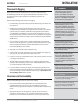
TABLE OF CONTENTS CAL-IOM-2014-0129 Introduction 1-1 Overview .............................................................................................................. 1-2 Warnings & Cautions............................................................................................ 1-2 Disclaimers and Local Codes ................................................................................ 1-2 Installation 2-1 Product Overview..................................................................
TABLE OF CONTENTS 0-2 CAL-IOM-2014-0129 © The Fulton Companies 2014
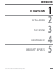
INTRODUCTION INTRODUCTION INSTALLATION OPERATION MAINTENANCE WARRANTY & PARTS Questions? Please Contact Your Local Manufacturer’s Representative 1 2 3 4 5 1-1
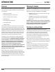
INTRODUCTION CAL-IOM-2014-0129 SECTION 1 Overview Warnings & Cautions Prior to shipment, the following inspections and tests are made to ensure the highest standards of manufacturing for our customers: WARNINGS and CAUTIONS appear in various chapters of this manual. It is critical that all personnel read and adhere to all information contained in WARNINGS and CAUTIONS. Material inspections WARNINGS must be observed to prevent serious injury or death to personnel.
INSTALLATION INTRODUCTION INSTALLATION OPERATION MAINTENANCE WARRANTY & PARTS Questions? Please Contact Your Local Manufacturer’s Representative 1 2 3 4 5 2-1
INSTALLATION ! WARNING All information in this manual is for reference and guidance purposes, and does not substitute for required professional training, conduct, and strict adherence to applicable jurisdictional/professional codes and regulations. CAL-IOM-2014-0129 SECTION 2 Product Overview Prior to the performance of installation, operation, or maintenance procedures, personnel should become familiar with the equipment (Table 1 and Figure 1) and its components.
SECTION 2 INSTALLATION CAL-IOM-2014-0129 Placement & Rigging Proper placement of your Fulton product is essential. Attention paid to the following points will save a great deal of difficulty in the future. Correct placement is the first step to trouble-free installation, operation, and maintenance.
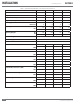
INSTALLATION CAL-IOM-2014-0129 SECTION 2 TABLE 1 - OPERATING REQUIREMENTS (SEE TABLE NOTES ON PAGE 2-5) Caliber Model Size 300 500 750 850 Input (BTU/Hr) 300,000 500,000 750,000 850,000 Output (BTU/Hr) 283,500 472,500 708,750 803,250 Natural Gas Consumption (ft3/hr) 297 495 743 842 Propane Consumption**(ft3/hr) 120 200 300 340 Minimum Maximum 4.0 14 4.0 14 4.0 14 4.
SECTION 2 INSTALLATION CAL-IOM-2014-0129 C X H G Outlet D J B G Inlet Y I A Front View Back View Right Side View * Refer to Figure 2 FIGURE 1 -CALIBER HYDRONIC BOILER 36" 24" 36" 6" 24" 6" 24" FIGURE 2 -CALIBER HYDRONIC BOILER SIDE CLEARANCES Table 1 Notes: Specifications and dimensions are approximate. We reserve the right to change specifications and dimensions without notice. *See Figure 1.
INSTALLATION ! WARNING The discharge from the safety relief valve must be arranged to ensure no danger to personnel or equipment damage. Provisions must be made to properly pipe the safety relief discharge away from the boiler to the point of discharge. No shutoff of any kind shall be placed between the safety relief valve and the boiler, or in the discharge pipe between the valve and the atmosphere. Doing so may cause an explosion from overpressure.
SECTION 2 INSTALLATION CAL-IOM-2014-0129 ideal flow rates for the Caliber boiler. to heating coils (located in air handling units where they may be exposed to refrigerated air circulation), such boiler piping systems shall be equipped with flow control valves or other automatic means to prevent gravity circulation of the boiler water during the cooling cycle.
INSTALLATION CAL-IOM-2014-0129 SECTION 2 FIGURE 3 - SAMPLE PIPING LAYOUT: SINGLE BOILER WITH PRIMARY/SECONDARY PIPING CONFIGURATION 2-8 © The Fulton Companies 2014
SECTION 2 CAL-IOM-2014-0129 INSTALLATION FIGURE 4 - SAMPLE PIPING LAYOUT: MULTIPLE BOILERS IN A COMMON HYDRONIC LOOP, PRIMARY/SECONDARY WITH REVERSE RETURN Questions? Please Contact Your Local Manufacturer’s Representative 2-9
INSTALLATION CAL-IOM-2014-0129 SECTION 2 FIGURE 5 - SAMPLE PIPING LAYOUT: MULTIPLE BOILERS IN A COMMON HYDRONIC LOOP, INDIRECT DOMESTIC HOT WATER 2-10 © The Fulton Companies 2014
SECTION 2 INSTALLATION CAL-IOM-2014-0129 3. Appropriate flow rates may be achieved through primary and secondary flow loops. Please refer to Figures 3 - 5 for example systems. Multiple pumps, valves and heating zones operating at a variety of conditions will cause system flow to vary. System design professionals should consider the variety of conditions the heating system will experience. 4. Operate the boiler in a closed-loop system using water or water/glycol (not requiring a make-up water supply).
INSTALLATION ! WARNING All information in this manual is for reference and guidance purposes, and does not substitute for required professional training, conduct, and strict adherence to applicable jurisdictional/ professional codes and regulations. 4 CAUTION Some soap used for leak testing is corrosive to certain types of metals. Clean all piping thoroughly after completing the leak check. Never leave an opened manual air vent unattended.
SECTION 2 INSTALLATION CAL-IOM-2014-0129 8. Again, open manual air vents at high points of heating loop until a constant stream of water is discharged from the vent. Close the vent and make sure it’s watertight. Repeat procedure for all high points and for every zone. 9. Due to the nature of the heat exchanger utilized in the Caliber Hydronic Boiler, pockets of air may still be trapped in the heat exchanger.
INSTALLATION CAL-IOM-2014-0129 SECTION 2 installation is started, carefully check all piping connections(factory and field) for gas leaks. Use a soap and water solution. 2. Piping must be installed such that no piping stresses are transmitted to the boiler. The boiler cannot be used as a pipe anchor. 3. The boiler and all gas piping connections must be pressure-tested and checked for leaks before being placed into service. Test with compressed air or inert gas, if possible. 4.
SECTION 2 INSTALLATION CAL-IOM-2014-0129 Venting Adhere to the following venting requirements: 1. The boiler can be installed with either sealed combustion or a conventional venting arrangement. With either venting configuration, the difference in pressure readings at the boiler exhaust connection and air intake connection cannot exceed 1.0” W.C. This equates to 70 feet (21.
INSTALLATION ! WARNING All information in this manual is for reference and guidance purposes, and does not substitute for required professional training, conduct, and strict adherence to applicable jurisdictional/professional codes and regulations. Do not use the boiler/burner as support for ducted air piping. Ducted piping must be supported independently of the boiler. Do not terminate venting into an enclosed area.
SECTION 2 INSTALLATION CAL-IOM-2014-0129 is used, the first 8 inches (204 mm) must be CPVC material. Venting installation must comply with National Fuel Gas Code, ANSI Z233.1, Part 10 or applicable provisions of local building codes. 2. Do not utilize automatic vent dampers or barometric dampers with the Caliber boiler. Because the exhaust system operates at a positive pressure, utilizing dampers could result in exhaust gases leaking into the boiler room. 3.
INSTALLATION CAL-IOM-2014-0129 SECTION 2 FIGURE 7 - COMBUSTIBLE WALL PENETRATION DETAILS Common Air Intake and Exhaust Venting of Multiple Boilers check valve to close and prevent flue gases from recirculating through an idle boiler. This component is required when Caliber boilers are common vented. Combining multiple Caliber boilers into a common pipe for combustion air supply, exhaust, or both is only permitted on a case by case basis and must be accomplished with a Fultonengineered solution.
SECTION 2 INSTALLATION CAL-IOM-2014-0129 FIGURE 8 - VENTING CONFIGURATIONS Intake Duct Sizing Adhere to the following: 1. Air intake ducting must be sized in conjunction with the exhaust venting to provide no greater than a 1.0” W.C. combined pressure drop. This equates to 70 feet and 8 elbows when combining the distances on the air intake and exhaust with the piping diameters matching the standard connections.
INSTALLATION ! WARNING Use of automatic vent dampers or barometric dampers with the Caliber boiler in positive pressure systems may result in exhaust leaking into the boiler room. It is critical to fill the condensate trap with water prior to the first time the boiler is started up. Failure to do so could allow flue gas products into the boiler installation space, resulting in personal injury or death. he exhaust vent installer should be familiar with Federal Codes as well as local codes and regulations.
SECTION 2 INSTALLATION CAL-IOM-2014-0129 upward pitch can be maintained. 6. When penetrating a non-combustible wall, the hole through the wall must be large enough to maintain the pitch of the vent and provide sealing. Use adhesive material to seal around the vent on both sides of the wall. When penetrating a combustible wall, a wall thimble must be used. See Figure 8 for installation instructions. Minimum wall thickness through which vent system may be installed is 3.25 inches (82.5 mm).
INSTALLATION ! WARNING All information in this manual is for reference and guidance purposes, and does not substitute for required professional training, conduct, and strict adherence to applicable jurisdictional/professional codes and regulations. CAL-IOM-2014-0129 SECTION 2 4. Seal the pipe to the thimble flange with adhesive material. 5.
SECTION 2 INSTALLATION CAL-IOM-2014-0129 SCREW OR BOLT EACH THUMBLE COLLAR TO WALL (TYPICAL 4 PLACES) ORIENT COLLAR AND CLAMPS AS REQUIRED PIPE RETAINING CLAMP, TYPICAL EACH SIDE END VIEW 3 1/2 IN. OR 4.35 CM AIR GAP ALL AROUND THRU PIPE DIAMETER "C" STAINLESS DIAMETER "B" ADJUSTABLE WALL THUMBLE WIDTH TO VARY WITH WALL THICKNESS DIAMETER "A" COLLAR VARIABLE (3 1/4 IN. MIN.) - (20 IN. MAX.) (8.255 CM MIN. - 50.8 CM MAX.
INSTALLATION CAL-IOM-2014-0129 SECTION 2 Electrical Connections Adhere to the following when installing electrical connections: 1. Install wiring and ground boiler in accordance with authority having jurisdiction, or in absence of such requirements utilize National Electrical Code, ANSI/ NFPA 70. 2. This boiler requires an independent 120V 60Hz single phase connection. Connect power to the terminal strip as supplied on the inside cover of the panel box. 3.
SECTION 2 CAL-IOM-2014-0129 Questions? Please Contact Your Local Manufacturer’s Representative INSTALLATION 2-25
INSTALLATION CAL-IOM-2014-0129 SECTION 2 A B C FIGURE 12 - EXAMPLE ELCTRICAL DRAWING - FOR REFERENCE PURPOSES ONLY 2-26 © The Fulton Companies 2014
SECTION 2 1 3 7 6 8 11 5 10 INSTALLATION CAL-IOM-2014-0129 NOTES: 1. ( ) DENOTES FIELD WIRING BY OTHERS. 2. REMOVE FACTORY INSTALLED JUMPER FOR E-STOP CONNECTION. 3. FOR BMS INTERFACE IF LEAD/LAG IS USED, USE COM2 ON DISPLAY, IF STAND ALONE BOILER OR LEAD/LAG IS NOT USED BMS CONNECTS TO J3-MB1. 4. PB1 IS A COMBINATION PILOT LIGHT - PUSH BUTTON ASSEMBLY.
INSTALLATION 2-28 CAL-IOM-2014-0129 SECTION 2 © The Fulton Companies 2014
OPERATION INTRODUCTION INSTALLATION OPERATION MAINTENANCE WARRANTY & PARTS Questions? Please Contact Your Local Manufacturer’s Representative 1 2 3 4 5 3-1
OPERATION ! WARNING All information in this manual is for reference and guidance purposes, and does not substitute for required professional training, conduct, and strict adherence to applicable jurisdictional/ professional codes and regulations. Failure to follow instructions may result in a fire or explosion, causing property damage, personal injury, or loss of life. This boiler is equipped with an ignition device, which automatically lights the burner. Do not try to light the burner by hand.
SECTION 3 OPERATION CAL-IOM-2013-1001 3. Review the unit-specific control schematics, and follow appropriate instructions. Test of Ignition Safety System Test the ignition system safety shutoff as follows: 1. Remove the black plug/connector from the main gas valve (it is attached with a central screw). 2. With the main gas cock (inlet manual gas valve) open, a call for heat will cycle the burner on.
OPERATION ! WARNING Non-Fulton product information is for reference purposes only. No Fulton document should substitute for full review of documentation available from the component manufacturer. CAL-IOM-2013-1001 SECTION 3 boiler locks out. This condition has to be manually reset. Alter the high limit setpoint temperature to normal level, typically 10-20 degrees above set point.
SECTION 3 OPERATION CAL-IOM-2013-1001 equipment. Caliber boilers should be operated and controlled so that the boiler cycles less than 12,000 times per year. Outlet water temperature, fan speed and set point are displayed on the SOLA touch screen display on the front of the boiler. Figure 14 shows a sample Status Screen display on the SOLA control. ! WARNING Non-Fulton product information is for reference purposes only.
OPERATION ! WARNING Non-Fulton product information is for reference purposes only. No Fulton document should substitute for full review of documentation available from the component manufacturer. CAL-IOM-2013-1001 SECTION 3 3. Tap the yellow background rpm box next to firing rate. (See Figure 16). 4. Under Firing Rate Control, tap Manual in Run. Refer to Figure 17. This boiler is equipped with an ignition device which automatically lights the burner. Do not try to light burner by hand.
SECTION 3 OPERATION CAL-IOM-2013-1001 5. Using test fire sheet, enter the rpm value (light off ) in the Manual Firing Rate box. 6. Once the rpm value is entered, tap OK. 7. Return to the status screen. 8. Turn the local/off/remote switch to the local position. 9. Once burner has started and flame signal has been verified, return to the Manual Firing Rate box. 10. Increase the firing rate in 500 rpm increments until high fire rpm value from the factory test fire sheet is reached.
OPERATION CAL-IOM-2014-0129 SECTION 3 2. Close all manual gas valves. 3. Turn off electrical power. Emergency Shut Off Procedures The main gas cock should be closed immediately. If overheating occurs or the gas supply fails to shut off, do not turn off or disconnect the electrical supply to the pump. Instead, shut off the gas supply at a location external to the boiler. Shutting the Boiler Down for an Extended Period of Time If the boiler is to be shut off for a period greater than 3 months: 1.
SECTION 3 CAL-IOM-2014-0129 OPERATION SOLA Control Features Refer to the Table below for additional SOLA Control screen displays. Viewing the Flame Signal 1. The flame signal can be viewed from the main/home screen or in main screen details. 2. Tap Details in main screen, then scroll to right by pressing the arrow until Flame Detection is displayed. 3. Tap the escape arrow in top right hand corner to return to main operating screen.
OPERATION CAL-IOM-2014-0129 SECTION 3 Delta T Limit The maximum Delta T is 60 F.
MAINTENANCE INTRODUCTION INSTALLATION OPERATION MAINTENANCE WARRANTY & PARTS Questions? Please Contact Your Local Manufacturer’s Representative 1 2 3 4 5 4-1
MAINTENANCE ! WARNING All information in this manual is for reference and guidance purposes, and does not substitute for required professional training, conduct, and strict adherence to applicable jurisdictional/professional codes and regulations. Prior to any maintenance concerning electrical components of this equipment, ensure electrical supply to the equipment is disconnected. Label all wires prior to disconnection; wiring errors may cause improper and hazardous operation.
SECTION 4 MAINTENANCE CAL-IOM-2014-0129 5. Test the water flow switch by trying to restart boiler with system pump off. The boiler should not operate. 6. If an air inlet filter is included with the boiler, inspect and clean filter of any dust or lint. See Procedure for Cleaning the Air Inlet Filter. 7. Verify that the water loop style traps in the exhaust venting system are flooded.
MAINTENANCE ! WARNING Follow proper lockout / tag out procedures for the electrical, gas and water connections. Use caution when lifting heavy parts. Never use open flame or other sources of ignition to check for gas leaks. 4 CAUTION All information in this manual is for reference and guidance purposes, and does not substitute for required professional training, conduct, and strict adherence to applicable jurisdictional/professional codes and regulations.
SECTION 4 MAINTENANCE CAL-IOM-2014-0129 13. Before re-installing the burner, check the cleanliness of the heat exchanger and the condition of the combustion chamber. If corrosion or leaks are noticed, contact Fulton Heating Solutions. 14. Reverse removal steps for reinstallation of the burner assembly. 15. Reinstall front and side jacket panels. 16. Test fire the boiler and use a combustion analyzer to ensure that the fuel/ air ratio is set correctly throughout the range.
MAINTENANCE ! WARNING All information in this manual is for reference and guidance purposes, and does not substitute for required professional training, conduct, and strict adherence to applicable jurisdictional/professional codes and regulations. CAL-IOM-2014-0129 SECTION 4 Troubleshooting Use the following tables as a guide to troubleshooting your boiler. If any manual reset limit device trips, do not reset without determining and correcting the cause.
SECTION 4 MAINTENANCE CAL-IOM-2014-0129 PROBLEM CAUSE CHECK/SOLUTION Manual Reset limit device trips Manual Reset Limits include: Flame safeguard, high or low gas pressure, high temperature limit DO NOT reset without determining and correcting the cause. Contact your local representative/ qualified service technician. Power outage to the boiler room Entire boiler system is disabled and de-energized.
WARRANTY & PARTS INTRODUCTION INSTALLATION OPERATION MAINTENANCE WARRANTY & PARTS Questions? Please Contact Your Local Manufacturer’s Representative 1 2 3 4 5 5-1
PARTS & WARRANTY ! WARNING Use of non-factory authorized replacement parts is not recommended for this equipment. Use of non-factory authorized parts may jeopardize safety and system performance, and voids the product warranty. 5-2 CAL-IOM-2014-0129 SECTION 5 Parts Spare and replacement parts may be ordered from your local representative or through the Fulton Companies. When ordering replacement parts, please have the model number and serial number of your Fulton boiler ready.
SECTION 5 CAL-IOM-2014-0129 WARRANTY & PARTS Standard Warranty for Fulton Caliber Hydronic Boilers Warranty Valid for all Caliber Models Ten (10) Year Thermal Shock Warranty The Caliber pressure vessel is warranted against failure due to thermal shock for a period of Ten (10) years from the date of shipment from the factory. This warranty does not cover damage due to corrosion, scaling, sooting and/or improper installation, operation and maintenance.
WARRANTY & PARTS CAL-IOM-2014-0129 SECTION 5 THIS PAGE INTENTIONALLY LEFT BLANK 5-4 © The Fulton Companies 2014
SECTION 5 WARRANTY & PARTS CAL-IOM-2014-0129 THIS PAGE INTENTIONALLY LEFT BLANK Questions? Please Contact Your Local Manufacturer’s Representative 5-5
WARRANTY & PARTS CAL-IOM-2014-0129 SECTION 5 THIS PAGE INTENTIONALLY LEFT BLANK 5-6 © The Fulton Companies 2014
No part of this Installation, Operation, and Maintenance manual may be reproduced in any form or by any means without permission in writing from the Fulton Companies. Fulton Boiler Works, Inc., Fulton Heating Solutions, Inc. & Fulton Thermal Corporation are part of the Fulton Group of Companies, a global manufacturer of steam, hot water and thermal fluid heat transfer systems. © The Fulton Companies 2014 The heat transfer innovators.