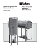
Installation Operation And Maintenance Manual November 2006 Fulton Horizontal and Vertical Return Systems
Section 1 2 3 4 Safety Warnings and Precautions PAGE 3 Installation and Operation PAGE 7 Maintenance PAGE 13 Parts & Warranty PAGE 17 RTN IOM 1
2 RTN IOM
Section 1 2 3 Safety Warnings and Precautions RTN IOM 3
Safety Warnings and Precautions This manual is provided as a guide to the correct operation and maintenance of your Fulton Condensate Return System and should be permanently available to the staff responsible for the operation of the return system. These instructions must not be considered as a complete code of practice, nor should they replace existing codes or standards which may be applicable.
Safety Warnings and Precautions For Your Safety The following WARNINGS, CAUTIONS, and NOTES appear in various sections of this manual. They are repeated on these safety summary pages as an example and for emphasis. WARNINGS must be observed to prevent serious injury, or death to personnel. CAUTIONS must be observed to prevent damage or destruction of equipment or loss of operating effectiveness.
6 RTN IOM
Section 1 2 3 Installation and Operation RTN IOM 7
8 RTN IOM
Installation and Operation Installation Location The condensate return system should be located to permit access to operating controls, instruments and inspection openings. Figure 1 The foundation should be level and designed to support the load. Calculations should be based upon the maximum or filled weight of the system. Rigging Qualified riggers should be used to place the system on the foundation.
Installation and Operation NOTE 5. Install the bottom gauge fitting (the fitting with a drain valve) until it is snug and the glass outlet is pointing directly upward. Verify top and bottom fittings are threaded into the tappings the same number of turns (distance A - distance B). Only properly trained personnel should install and maintain water gauge glass and connections. Wear safety glasses during installation. Before installing, make sure all parts are free of chips and debris.
Installation and Operation Figure 4 Figure 5 Inlet Inlet Valve Open Valve Open Pivot Points Pivot Points Discharge Opening Ball Position Lock Ball Position Lock Discharge Opening Float Ball Float Ball Wiring Accessories System Start Up 1. Check voltage, phase and hertz available against motor nameplate for compatibility. Optional accessories should be installed in accordance with the manufacturer’s instructions. 1. Inspect all pipe connections to be sure they are secure.
12 RTN IOM
Section 1 2 3 Maintenance RTN IOM 13
14 RTN IOM
Maintenance Maintenance 1. Inspect all controls for proper operation. Lubricate all moving parts as required. 2. Clean and check water gauge glass for presence of oil. If detected, find the source and eliminate it. seal if necessary folloiwn the pump manufacturer’s instructions. 4. Pump bearings may or may not require lubrication depending on a particular pump. Follow the pump manufacturer’s instructions.
16 RTN IOM
1 2 Section 4 Parts & Warranty RTN IOM 17
Parts Part Number Description 7-75-000 7-75-002 7-75-004 7-75-006 7-75-008 7-75-010 7-75-012 7-75-014 7-75-016 7-75-017 7-75-018 7-75-019 7-75-021 7-75-022 7-75-023 7-75-024 7-75-025 7-75-026 7-75-027 7-75-028 7-75-035 7-75-100 7-75-104 7-75-106 7-75-108 7-75-110 7-75-112 7-75-114 7-75-116 7-75-040 7-75-042 7-75-044 7-75-046 7-75-048 7-75-122 7-75-124 7-75-126 7-75-128 7-75-130 7-75-132 7-75-134 7-75-136 7-75-118 7-75-119 7-75-120 7-75-058 4-75-158 4-75-159 4-75-166 4-75-010 4-75-012 4-75-188 4-75-189 2-3
Parts Part Number Description 2-12-534 2-12-535 2-12-536 2-30-124 2-11-000 2-11-001 2-30-362 2-40-113 2-30-205 2-30-363 2-30-364 2-30-365 2-30-366 2-30-367 2-30-368 2-30-369 2-30-370 2-60-139 123 2-30-380 2-30-381 2-30-442 2-30-383 2-30-371 2-30-372 2-30-373 2-30-374 2-30-375 2-30-376 2-30-377 2-30-378 2-30-382 2-30-349 2-30-351 2-30-468 2-30-352 2-30-353 2-30-355 2-30-356 2-30-357 2-30-360 2-30-361 2-30-379 2-30-471 2-30-1100 2-30-472 2-30-1101 2-30-1103 2-30-1104 2-30-1107 2-30-1108 2-30-1110 2-30-1111
20 RTN IOM
Standard Warranty for Fulton Return Tanks Warranty Valid for Models HT and VT 1-Year (12 Months) Material and Workmanship Warranty Fulton Thermal Corporation will repair or replace F.O.B. factory any pressure vessel, which within one (1) year of the date of shipment from the factory, is found to be defective in material or workmanship, provided this equipment has been installed, operated and maintained by the buyer in accordance with approved practices and recommendations made by Fulton.
Fulton Thermal Corporation 972 Centerville Road Pulaski, New York USA 13142 Call 315-298.5121 Fax 315-298.6390 www.fulton.com 22 RTN IOM No part of this Installation, Operation, and Maintenance manual may be reproduced in any form or by any means without permission in writing from the Fulton Companies.