XG2600 Hardware Guide Introduction xxxx-xxxx-xxxx XG2600 Hardware Guide
XG2600 Hardware Guide Preface You have purchased the XG2600, a compact, 26 port 10 Gigabit Ethernet layer 2 switch that achieves unsurpassed standards of high throughput and low-latency performance. This manual explains the procedures required to install your XG2600 and should be read and understood before you start using your XG2600. First edition: Jun 2009 This manual contains the technology regulated by "Foreign Exchange and Foreign Trade Control Law.
XG2600 Hardware Guide Contents Contents Preface ................................................................................................................................................................2 Organization and Usage of This Manual ............................................................................................................5 About This Manual ......................................................................................................................................
XG2600 Hardware Guide 2.4 2.5 2.6 Contents Connecting a Setup PC ..........................................................................................................................50 Time Setting ...........................................................................................................................................54 Set up IP address ....................................................................................................................................55 Index.....
XG2600 Hardware Guide Organization and Usage of This Manual This manual explains what you need to know before using this device. In addition, the README file on CD-ROM contains important information. You will also need to read the file. About This Manual This manual contains important information required to use this device safely. Read this manual thoroughly before using this device.
XG2600 Hardware Guide Trademark Notification in This Manual Microsoft, MS-DOS, Windows, Windows NT, Windows Server and Windows Vista are registered trademarks of the Microsoft Corporation in the USA and other countries. Adobe and Reader are trademarks or registered trademarks of Adobe Systems Incorporated in the USA and other countries. Netscape is a trademark of Netscape Communications Corporation in the USA. UNIX is a registered trademark of Open Group in the USA and other countries.
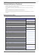
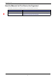
XG2600 Hardware Guide How the Manuals for This Device Are Organized The manuals for this device are organized as follows. Use these manuals as necessary. Manual Name Description XG2600 Hardware Guide (This manual) This manual describes the hardware of the XG2600. User’s Guide This manual describes a variety of operations and procedures, including the installation and maintenance of the XG Series.
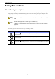
XG2600 Hardware Guide Safety Precautions About Warning Descriptions This manual contains precautions that must be taken in order to use this device safely and prevent personal injury or property damage. Please fully understand the meanings and contents of the following descriptions and symbols when reading this manual. Warning Caution Indicates that improper use can cause severe damage to person, resulting in serious injury or death. Indicates that improper use can cause light or moderate injury.
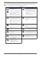
XG2600 Hardware Guide Warning Always follow the instructions for safe use of this device. Indicates that improper use can cause severe damage to person, resulting in serious injury or death. Warnings Do not insert or drop any foreign objects into the device through the vent. Also, prevent liquid such as water from entering it. In case a foreign object or liquid enters the device, you must first unplug the power plug from the socket and contact our engineer or an engineer certified by Fujitsu.
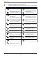
XG2600 Hardware Guide Caution Indicates that improper use can cause light or moderate injury. In addition, this symbol indicates a chance of damage to this device and other connected equipment. Cautions Do not touch this device for more than one minute while it is turned on. Failure to follow this may cause low-temperature burns. Do not put objects on this device or use it as a work area. Failure to follow this may cause damage to the device , or result in injury to person or failure.
XG2600 Hardware Guide Notes on Maintenance • Customers should not repair this device. In the event of failure, consult our engineer or an engineer certified by Fujitsu for maintenance. • Do not dismantle or modify this device for any reason. This device contains high voltage and high temperature parts that can be dagerous. Precautions for Use • As a guideline, you can use this device in stable state for five years, if it is operated within the guaranteed operation temperature range.
XG2600 Hardware Guide Cleaning When cleaning the device, please wipe with a cloth firmly wrung out of water (or watered-down neutral detergent). Please be careful so that water does not get into the device or gap when wiping. Static electricity Under certain conditions, twisted pair cables can become charged with static electricity. Connecting a statically charged twisted pair cable to the XG2600 can cause the device or its LAN port to operate falsely or to become damaged.
XG2600 Hardware Guide Laser safety The XG2600 may be installed with optical transceiver modules (SFP+ modules), which emit invisible laser light. In the USA, these optical modules are certified as Class 1 laser products that conform to the requirements of the Department of Health and Human Services (DHHS) regulation 21 CFR, Subchapter J. This certification is indicated by a label attached to each optical module.
XG2600 Hardware Guide Notes on Use Note the following points when using this device. • Manage and store the configuration for this device yourself after configuration is completed. If you ask Fujitsu to perform restore works in case of failure, our engineer needs to use the configuration managed and stored by you. If you do not provide the configuration for us, it can take time to restore the device. Please make a backup for the configuration as required to manage and keep the latest information.
Chapter 1 Getting Started This chapter lists the items that should be in the product package, and describes the names and functions of the various components. 1.1 Items in the Package / Names and Functions . . . . . . . . . . . . . . . . . . . . . . . . . . . . . . . . . . . . . . . . . . . 16 1.1.1 Parts List. . . . . . . . . . . . . . . . . . . . . . . . . . . . . . . . . . . . . . . . . . . . . . . . . . . . . . . . . . . . . . . . . . . 16 1.1.
XG2600 Hardware Guide 1.1 Chapter 1 Getting Started Items in the Package / Names and Functions Before proceeding, check all the items described below. 1.1.1 Parts List Please check all of the following parts are included in the package. XG2600 Power Cables (Qty 2) XG2600 Cable Holder (Qty 1) Console Cable SFP+ Dummy Caps (Qty 26) Rack Mounting Rails (1 set) M6 Countersunk Screws (Qty 4) M6 Machine Screws (Qty 6) CD-ROM EULA • XG2600 The XG2600 switch.
XG2600 Hardware Guide • Chapter 1 Getting Started SFP+ Dummy Caps (Qty 26) Dummy caps to prevent dust when the SFP+ slots are open and unplugged. The dummy caps come with the switch, installed on the slots at the time of purchase. • Rack Mounting Rails (1 set) Rails for mounting the switch in a rack. • M6 Countersunk Screws (Qty 4) Screws for fastening the rack rails to the front side of the rack.
XG2600 Hardware Guide 1.1.3 Chapter 1 Getting Started Switch Fan Unit Side MAC Firmware Label PSU Slots for Product Manufacturing Label Front-Access Configuration Fan Unit XG2600 FAN2 FAN1 PSU2 PSU1 • MAC Firmware Label This indicates the MAC addresses and firmware revision assigned to the switch. • Fan Unit This switch is installed with two Fan Units.
XG2600 Hardware Guide Chapter 1 Getting Started LED Functions/Behaviors LED Name READY CHECK STATUS OUTFLOW Light Status Green Switch has started up correctly. Green Blinking Switch is being diagnosed or operating under backup firmware. (*) Off A problem has occurred. Orange A problem has occurred which requires replacement. Orange Blinking Firmware in the internal flash memory of the switch is destroyed. Off Switch is in normal operation. Green Fan Unit is in normal operation.
XG2600 Hardware Guide 1.1.4 Chapter 1 Getting Started Switch Interface Side Serial Port PSU Slots for Rear-Access Installation PSU1 Power Supply Unit SFP+ Slots Reset Switch Port1 Port25 Port2 Port26 USB Port PSU2 Power Supply Unit Management Port Power Inlet • PSU Slots for Rear-Access Installation PSUs are plugged in the slots when the switch is used in Rear-Access configuration. • Power Inlet Plug the attached Power Cable in the package.
XG2600 Hardware Guide Chapter 1 Getting Started LED Details FLASH READY CHECK ERROR PSU1 PSU2 POWER Port2 SFP+ LINK/ACT Port1 SFP+ LINK/ACT FAN Port1 Port1 SFP+ Port2 SFP+ LINK/ ACT FDX Port2 • POWER LED Lights to indicate the status of PSU. • SFP+ LINK/ACT LED Lights to indicate the establishment of the link and status of the signal transmission. • SFP+ LED Lights to indicate the status of optical detection of the SFP+ slot. • READY LED Lights when the XG2600 is in an operable state.
XG2600 Hardware Guide Chapter 1 Getting Started LED Functions/Behaviors LED Name POWER SFP+ LINK/ACT SFP+ READY CHECK PSU1 PSU2 FAN FLASH ERROR LINK/ACT FDX Light Status Green PSU is in normal operation. Orange A problem has occurred with the PSU. Green SFP+ link is established. Green Blinking SFP+ is in communication. Off SFP+ link is not established. Green This indicates light detection of the SFP+ slot. Off This indicates light undetected of the SFP+ slot.
XG2600 Hardware Guide 1.1.5 Chapter 1 Getting Started Top Surface Rating Label Warning Sticker • Warning Sticker This indicates the warning for safety use. • Rating Label This indicates the rated voltage of the switch.
XG2600 Hardware Guide 1.2 Chapter 1 Getting Started How to attach Cable Holder (Cable Restraints with Tyraps) The Cable Holder prevents the power cable from being accidently pulled out of the switch. Below describes how to attach Cable Holder to the power code. Warning In case of installing the switch in a lockable rack and fixing the power cable with the attached Cable Holder, use service outlet in the rack.
XG2600 Hardware Guide Chapter 1 Getting Started 1.3 Option 1.3.1 SFP+ Module SFP+ modules (10GBASE-SR/10GBASE-LR) are available for use. Reference "2.3.3 Connecting Twisted Pair Cable / SFP+ Module" (pg.45) User’s Guide " SFP+ Module" (pg.
Chapter 2 Install ation This chapter describes how to install the switch and connect it to Console PC. 2.1 2.2 2.3 Requirements for Installation Environment . . . . . . . . . . . . . . . . . . . . . . . . . . . . . . . . . . . . . . . . . . . . . 27 2.1.1 Installation Requirements . . . . . . . . . . . . . . . . . . . . . . . . . . . . . . . . . . . . . . . . . . . . . . . . . . . . . 27 2.1.2 Space Requirements . . . . . . . . . . . . . . . . . . . . . . . . . . . . . . . . . . . . . . . . . . . .
XG2600 Hardware Guide 2.1 Chapter 2 Installation Requirements for Installation Environment Before installing the switch, please check the following: • Make sure that the switch and all the other options shown in this document are available for installation. • All the cables comply with the specifications of the interface connectors. Warning Do not connect cables to interface connectors other than those adaptable to the connector’s specifications. Reference "1.1.1 Parts List" (pg.
XG2600 Hardware Guide Chapter 2 Installation Installation Requirements The product is specifically designed for rack-mounting. Check-list Check the following items. Check Item Check Result Nothing is put on the switch. Vents are not obstructed. The switch is not located on the table or not stuck on another switch. The switch is not located under direct sunshine, near heating appliance, under high humidity or in a dusty area.. The switch is not located on unstable places where vibrating, or tilting.
XG2600 Hardware Guide 2.2 Chapter 2 Installation Installation of the switch This section describes how to install the switch. 2.2.1 Decide Switch Access Configuration The switch is specifically designed for rack-mounting. The switch can be installed in two different switch access configurations (airflow directions) in a rack. • Rear-Access Configuration (Factory Default) • Front-Access Configuration (User Configured) The following describes how to install each airflow configuration.
XG2600 Hardware Guide Chapter 2 Installation Caution • Do not install PSUs to face the front side of the rack. They do not work properly. • Before installing the switch in the rack, check if the airflow direction of the fans is correct. If the air flows incorrectly, it may cause failure to the switch The diagram below shows in which slots PSUs need to be installed and airflow direction of the fans.
XG2600 Hardware Guide Chapter 2 Installation Front-Access Configuration (User Configured) The interface side (SFP+ slots) is facing forward in a rack. Exhaust PSU1 PSU2 FAN1 Rack Rear FAN2 (Caution) (Caution) Intake Rack Front XG2600 Caution • Do not install PSUs facing the front side of the rack. They do not work properly • Before installing the switch in the rack, check if the airflow direction of the fans is correct. If the air flows incorrectly, it may cause failure to the switch.
XG2600 Hardware Guide Chapter 2 Installation The diagram below shows in which slots PSUs need to be installed and airflow direction of the fans.
XG2600 Hardware Guide 2.2.2 Chapter 2 Installation Rear-Access Configuration (Factory Default) This section describes how to install switch in Rear-Access configuration (Factory Default). Decide positions for rack mounting brackets 1. Decide positions of rack mounting brackets. It is possible to install the switch either in a standard front position of the rack or in an offset position of the rack. In case to locate the switch offset from the front side, change the positions of rack mounting brackets.
XG2600 Hardware Guide Chapter 2 Installation Install the switch in a 19” rack The switch can be installed and operated in the EIA standard 19" rack. Prepare the following rack mounting components attached. • Rack Mounting Rails (1 set): Rails for mounting the switch in a rack. • M6 Countersunk Screws (Qty 4) • M6 Machine Screws (Qty 6) Reference "1.1.1 Parts List" (pg.16) Precautions • When installing the switch in the rack, separately procure screws according to the specifications of the rack.
XG2600 Hardware Guide 2. Chapter 2 Installation Slide the switch between rails which are fixed to the rack, and fasten the 2 M6 screws to the front posts. XG2600 M6 Machine Screws M6 Machine Screws Precautions Pre-occupied devices in the upper and/or lower row of the rack may interfere with the power cable of the switch from being properly installed. In that case, plug the power cable to the switch before install it in the rack.
XG2600 Hardware Guide 2.2.3 Chapter 2 Installation Change Switch Access Configurations from Rear-Access (Factory Default) to Front-Access and Install This section describes how to change Rear-Access configuration (Factory Default) to Front-Access. Note For Front-Access configuration to Rear-Access, make the procedure reversed. Remove rack mounting brackets 1. Remove rack mounting brackets attached to the sides of the switch.
XG2600 Hardware Guide 1. Chapter 2 Installation Loosen two screws to remove fan unit. XG2600 Screw 2. Screw Remove fans (1) Remove two screws. (2) Unlock Cable Holder (which prevents cables from being pulled out). (3) Remove cables (3) (2) 3. (1) Change direction of fans. (1) Turn over the fan.
XG2600 Hardware Guide Chapter 2 Installation (2) Check if the direction shown in Airflow Label matches the airflow direction required. (3) Unlock Cable Holder to which the cable is connected. (4) Lock the unused Cable Holders. (3) (2) (4) 4. Fix fans. (1) Fasten screws. (2) Connect cables. (3) Lock Cable Holder for the connected cables to prevent the cable from being accidently pulled out. (3) (1) (2) 5. Insert back the Fan unit in the fan slot and fasten two screws to fix it to the switch.
XG2600 Hardware Guide Chapter 2 Installation Change PSU’s positions to meet different switch access configurations There are two types of PSU Slot Bezel. • PSU Bezel (Vents with Logo) Put it to empty PSU1 slot. • PSU Bezel (Vents without Logo) Put it to empty PSU2 slot right next to PSU1 slot. XG2600 Vents with Logo Vents without Logo The procedure to change PSU configurations is shown below. 1. Remove screws to take off two PSU slot bezels on the Fan Unit side (PSU1 and PSU2 slots).
XG2600 Hardware Guide 3. Chapter 2 Installation Put PSU Bezel (Vents with Logo) to PSU1-slot on the Interface Side with screws. Put PSU Bezel (Vents without Logo) to PSU2-slot right next to PSU1 slot with screws. XG2600 4. Slide PSUs into PSU1-slot and PSU2-slot and fix them to the switch with screws.
XG2600 Hardware Guide Chapter 2 Installation Attach rack mounting brackets to the switch 1. Attach rack mounting brackets to fit either a standard front position of the rack or a offset position of the rack. [STANDARD] XG2600 Plug into the hole of the device. [OFFSET] XG2600 Rack Mounting Clamps Precautions PSUs have to always be located in the rear side of the rack. If the position of PSUs is not appropriate, rack mounting brackets cannot be attached to the switch properly.
XG2600 Hardware Guide 2.3 Chapter 2 Installation Connecting the Equipment We recommend discharging static electricity of twisted pair cable before connecting it to the switch. See below for the procedure of discharging. Also see below for how to install USB memory. 2.3.1 Discharging Twisted Pair Cable Discharge static electricity of the twisted pair cable through the ground wire cable (ground wire for power supply, buildings, etc.
XG2600 Hardware Guide 2.3.2 Chapter 2 Installation Cleaning SFP+ Module / Optical Connector When invisible small dust is adhered to SFP+ module /optical connector, optical signal will be shut or space caused by dust will impede transmission of optical signal. Therefore, clean up SFP+ module /optical connector before connection. Cleaning of SFP+ Module 1. Blow dust away with cleanly dry air or nitrogen. Check end face, and conduct operation below if dust is left. 2.
XG2600 Hardware Guide Chapter 2 Installation Removal of Micro Dust Remove micro dust on the optical fiber part following the method below if necessary. 1. Wipe the optical fiber part with ethanol or cleaning fluid. 2. Softly and slowly wipe the optical fiber part with cleaning fabric. 3. Wipe with a new cleaning stick in the same fashion, and dry the optical connector. Caution • Do not use fluid such as bleach because it will damage optical coupling.
XG2600 Hardware Guide 2.3.3 Chapter 2 Installation Connecting Twisted Pair Cable / SFP+ Module Below is how to connect twisted pair cable and SFP+ module. Use straight cable when connecting with routers and terminals. Use crossing cable in case of cascading connection with other switching HUBs with transmission mode at fixed setting other than auto negotiation. straight cable optical cable crossing cable Management port of the switch is set auto negotiation enable by default.
XG2600 Hardware Guide Chapter 2 Installation Connecting SFP+ Module Firmly install SFP+ module to SFP+ slot and lock module to the switch. SFP+ module Precautions • Safely keep a guard cap of SFP+ module. • Make sure to clean the end face of SFP+ module / optical cable before connecting optical connector because the end face may possibly be contaminated. • Do not directly touch the contact part of SFP+ module by hands. Use wristbands when touching SFP+ module.
XG2600 Hardware Guide Chapter 2 Installation Precautions Cable length will be as below based on the specification of the optical fiber cable. Type MMF Core/Cladding Diameter 62.5/125µm 50/125µm Minimum Transimission Band Cable Length (m) 160MHz/km 26 200MHz/km 33 400MHz/km 66 500MHz/km 82 2000MHz/km 300 Use the appropriate cable according to the installation place. Replacing SFP+ Module Precautions It is possible to install/replace SFP+ module with the power on.
XG2600 Hardware Guide 3. Chapter 2 Installation Connect optical cable and release the “disable status” of the SFP+ slot. • In case of using telnet or console Enter replacing SFP+ slot number in # online ether • 4. In case of using www browser Make the SFP+ slot number at the selective state by "Setting of physical port" of settings menu. Select "Use" of "Use of physical port", and click "Regist" icon.
XG2600 Hardware Guide 2.3.4 Chapter 2 Installation Plugging in the USB Memory USB memory can be plugged in from the interface panel of the switch. Caution Do NOT unplug out the memory stick during access. It may result in crashing setting data. Precautions It is possible to plug/unplug SFP+ module with the power on. Plug in the USB Memory Please refer to the following instructions; 1. Firmly insert the USB memory to USB port on the interface panel of the switch.
XG2600 Hardware Guide 2.4 Chapter 2 Installation Connecting a Setup PC This is to connect a set up PC to the console port of the switch using RS232C cable. Necessary Hardware / Software Please prepare the hardware & software specified below to connect to the switch. • Personal Computer 1 unit of personal computer for setting up configuration is required. • RS232C cable (Cross, D-SUB9 pin) RS232C cable is required to connect the set up PC to the switch.
XG2600 Hardware Guide Chapter 2 Installation Turn on the Power Caution • Please use the power cable included in this product. Also, please do NOT use this power cable on other products. • If the power outlet does not match with the power cable plug, please use the change plug adapter. As a safety measure to prevent electrical shocks, please make sure to connect the ground wire of the change plug.
XG2600 Hardware Guide 3. Chapter 2 Installation POWER LED of PSU1 and PSU1 LED of the switch will light in green. Next, plug in the power cable to the power connecter of PSU2. The POWER LED of PSU2 and PSU2 LED of the switch will light in green. POWER PSU1 PSU2 Prepare a Setup PC Log on using the terminal software. 1. Start up the terminal software by using the set up PC. 2.
XG2600 Hardware Guide 8. Chapter 2 Installation Confirm “#” is shown on screen. If the key in the wrong password, "invalid password." will be displayed, then the "Login :" will be displayed again. Please repeat your process from item 5.
XG2600 Hardware Guide 2.5 Chapter 2 Installation Time Setting Make sure to set up the time before you do other settings of the switch. The time is not set at the initial timing of purchase. Please refer below command for setting up time manually using console or telnet. ● コマンド When setting time and date to be "Jan 1, 2009 12:30:00am" type in command # date 2009/01/01.
XG2600 Hardware Guide 2.6 Chapter 2 Installation Set up IP address Please set the IP address at times when it is required. Eg. When setting the switch through www browser or installing a firmware from the initial state of the purchase. The following commands show how to set up the IP address (ex. 192.168.1.1) ● Command (When connecting through management port) # configure # oob ip address 192.168.1.
XG2600 Hardware Guide Index Index C P Cable Holder ............................................................ 16 CD-ROM .................................................................. 17 CHECK LED ..................................................... 18, 21 Communication Software ......................................... 50 Connecting the Equipment ....................................... 42 Console Cable .......................................................... 16 Console port ....................
XG2600 Hardware Guide Index W Warning Sticker .......................................................
XG2600 Hardware Guide xxxx-xxxx-xxxx Issued on Jun, 2009 Issued by FUJITSU LIMITED Printed in Japan • The contents may be revised without prior notice. • Fujitsu assumes no liability for damages to third party copyrights or other rights arising from the use of any information in this manual. • No part of this manual may be reproduced in any form without the prior written permission of Fujitsu. • Manuals with missing or wrongly collated pages will be replaced free of charge.