
Installation Manual

En-1
INSTALLATION MANUAL
AIR CONDITIONER
PART NO. 9374983018-02
OPTIONAL PARTS
External control set
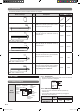
Contents
1. SAFETY PRECAUTIONS.......................................................................................................................................1
2. ABOUT THE UNIT
2.1. Accessories .....................................................................................................................................................2
3. SETTING
3.1. Setting (TYPE A) .............................................................................................................................................2
3.2. Setting (TYPE B) .............................................................................................................................................3
4. CONNECTING TO EXTERNAL DEVICE ............................................................................................................... 4
For authorized service personnel only.
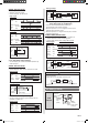
1. SAFETY PRECAUTIONS
WARNING
This mark indicates procedures which, if improperly performed, might lead to the death or serious
injury of the user.
•Wheninstallingeachwire,pleasethoroughlyreadthismanual.
•Beforeinstallationbesurethatallsourcesofpowerhavebeenshutoff.
There is a danger of electric shock.
•Usethevoltageasdescribedinthesignalspecications.
Usingvoltageofotherspecicationsmayresultinmalfunctionanderroneousoperationoftheairconditioner.
CAUTION
Thismarkindicatesprocedureswhich,ifimproperlyperformed,mightpossiblyresultinpersonal
harm to the user, or damage to property.
•Whenconnectingthewires,installtheinsulatingtubeorotherinsulatorontheconnection.
•Donotpullontheconnectorswithtoomuchforce.
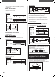
2. ABOUT THE UNIT
• SETTINGdependsonthePCBTYPEoftheindoorunit.CheckthePCBTYPEinthetablebelowandsetitup.
TYPE A TYPE B
PCB
LAYOUT
CN115
Operation
status output
(White)
CN106
Preparation
(Black)
CN5
Preparation
(Black)
CN14
Fan linked
Output
(Green)
CN15
Auxiliary
heater output
(Orange)
CN114
Start/stop
input
(White)
Indoor unit
PCB
Indoor
unit
PCB
CN10
Auxiliary
heater
output
(Orange)
CN103
Operation
status output
(White)
Indoor
unit
PCB
Indoor
unit
PCB
CN102
Start/stop
input
(White)
CN6
Fan linked
output
(Green)
SEE 3.1.Setting (TYPE A)
SEE 3.2.Setting (TYPE B)
9374983018-02_IM.indd 1 30/3/2552 13:23:59