PRIMERGY System Board D2530 for Econel 200 S2 Technical Manual Susanne Däschlein Fujitsu Siemens Computers GmbH München 81730 München e-mail: email: manuals@fujitsu-siemens.com Tel.
Comments… Suggestions… Corrections… The User Documentation Department would like to know your opinion of this manual. Your feedback helps us optimize our documentation to suit your individual needs. Fax forms for sending us your comments are included in the back of the manual. There you will also find the addresses of the relevant User Documentation Department.
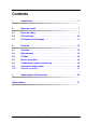
Contents 1 Introduction . . . . . . . . . . . . . . . . . . . . . . . . . . . . 5 2 Important notes . . . . . . . . . . . . . . . . . . . . . . . . . . 7 2.1 Notes on safety . . . . . . . . . . . . . . . . . . . . . . . . . . 7 2.2 CE Certificate . . . . . . . . . . . . . . . . . . . . . . . . . . 10 2.3 Environmental Protection . . . . . . . . . . . . . . . . . . . 11 3 Features . . . . . . . . . . . . . . . . . . . . . . . . . . . . . 13 3.1 Overview . . . . . . . . . . . . . . . . . . . . .
1 Introduction This technical manual describes the system board D2530, which can be equipped with one or two Intel® processors. Further information about drivers is provided in the readme files on the hard disk, on the supplied "ServerSupport" or "ServerStart" CDs. You will find further information in the BIOS description.
2 Important notes In this chapter you will find essential information regarding safety when working with your server. V CAUTION! With the system board installed you must open the system to access the system board. How to access the system board of your system is described in the appropriate service supplement. When handling the system board, refer to the specific notes on safety in the operating manual and/or service supplement for the respective server. 2.
Notes on safety V Important notes ● Components can become very hot during operation. Ensure you do not touch components when making extensions to the system board. There is a danger of burns! ● Transmisson lines to peripheral devices must be adequately shielded. ● To the LAN wiring the requirements apply in accordance with the standards EN 50173 and EN 50174-1/2.
Important notes Notes on safety Modules with electrostatic-sensitive components Systems and components that might be damaged by electrostatic discharge (ESD) are marked with the following label: Figure 1: ESD label When you handle components fitted with ESDs, you must observe the following points under all circumstances: ● You must always discharge yourself of static charges (e.g. by touching a grounded object) before working. ● The equipment and tools you use must be free of static charges.
CE Certificate Important notes Notes about boards ● During installation/deinstallation of the system board, observe the specific instructions described in the service manual for the server. ● Remove the plug from the mains outlet so that system and system board are totally disconnected from the mains voltage. ● To prevent damage to the system board, the components and conductors on it, please take great care when you insert or remove boards.
Important notes 2.3 Environmental Protection Environmental Protection Environmentally friendly product design and development This product has been designed in accordance with standards for ”environmentally friendly product design and development“. This means that the designers have taken into account important criteria such as durability, selection of materials and coding, emissions, packaging, the ease with which the product can be dismantled and the extent to which it can be recycled.
Environmental Protection Important notes Returning, recycling and disposal The device may not be disposed of with household rubbish. This appliance is labelled in accordance with European Directive 2002/96/EC concerning used electrical and electronic appliances (waste electrical and electronic equipment - WEEE). The guideline determines the framework for the return and recycling of used appliances as applicable throughout the EU.
Features Overview 3 Features 3.1 Overview Processors – 2 x Intel® Xeon™ Dual Core processors – 2 processor sockets Dual LGA771 for Intel® Xeon™ Dual Core processor with 1333/1066/667 MHz front side bus – supports Intel® Extended Memory 64 Technology (EM64T) – supports Intel® Hyper-Threading Technology (H.T.
Overview Features Internal connectors – – – – – – – – – – – – – – – – floppy disk 1 IDE primary 6 SATA connectors SATA-HDD access (HDLED) 2 USB connectors 1 serial port connector (COM2) PC98 connector 1 parallel port connector (LPT1) front panel main power connector (12V, -12V, 5V, 3.3V and 5V auxiliary) 12V (CPU) power connector 2 CPU fans 1 rear fan BPSMB connector BPSMB connector RAID key External connectors – – – – – 1 serial port (COM1) 2 PS/2 interfaces for keyboard and mouse 2 USB 2.
Features 3.2 Main memory Main memory The system board supports up to 8 Gbyte main memory. 4 slots (2 banks with 2 modules) are available for the main memory. Each memory bank can be populated with 512 Mbyte, 1 Gbyte or 2 Gbyte FBD533/PC2-4200F Fully Buffered DIMM memory modules. ECC with memory scrubbing and with the Single Device Data Correction (SDDC) function is supported. I You will find the descriptions how to install memory modules in the Options Guide of your server.
PCI bus 3.
Features PCI bus The PCI interrupts INTA#, INTB#, INTC# and INTD# are available for each PCI slot (except the PCI-Express slots). The same interrupt can be assigned simultaneously to several PCI boards. You should avoid this condition due to reduced performance. If you use a setting other than Auto, the Plug&Play functionality of the system BIOS for the corresponding PCI boards is deactivated. Auto The PCI interrupts are assigned automatically in accordance with the Plug&Play guidelines.
Screen resolution 3.4 Features Screen resolution Depending on the operating system used the screen resolutions in the following table refer to the screen controller on the system board. If you are using an external screen controller, you will find details of supported screen resolutions in the operating manual or technical manual supplied with the controller.
Features Temperature / system monitoring Fan control The fans are controlled according to temperature. Sensor monitoring The removal of, or a fault in, a temperature sensor is detected. Should this happen all fans monitored by this sensor run at maximum speed, to achieve the greatest possible protection of the hardware. Voltage monitoring The most important voltages are monitored. When a voltage exceeds warning level high or falls below warning level low an alert will be generated.
Connectors and jumpers 3.
Features Connectors and jumpers 7 = CPU2 fan 8 = RAID key 9 = SATA 1 - 6 10 = USB 7/8 11 = IDE primary 12 = HDLED 13 = intrusion 14 = front panel 21 = LPT1 22 = VGA_EN (jumper) 23 = CLRTC (jumper) 24 = LAN_EN (jumper) 25 = LAN_BW (jumper) 26 = rear fan 27 = external connectors A = 5V Standby LED Settings with jumpers The system board is supplied with all jumpers set on default position (pin 1-2).
Connectors and jumpers Features LAN_EN (24) 1-2 onboard LAN enabled (default) 2-3 onboard LAN disabled (PCI LAN controller) LAN_BW (25) 1-2 LAN bandwidth setting to balanced mode (default) 2-3 LAN bandwidth setting to centric mode LED 5V Standby(A) lightning green standby power present off 3.6.
Features Connectors and jumpers LAN connector On this system board you will find a LAN controller integrated in the Intel® 6321 I/O controller Hub (ICH). This controller is supported by an external chip (Intel® Single 1 GB PHY 82564EB), which is connected to the I/O controller Hub via an original Intel interface (Kumeran Interface). The LAN controller supports the transfer rates of 10 Mbit/s, 100 Mbit/s and 1 Gbit/s and supports WOL function through Magic Packet™.
4 Replacing the lithium battery In order to save the system information permanently, a lithium battery is installed to provide the CMOS-memory with a current. When the charge is too low or the battery is empty, a corresponding error message is provided. The lithium battery must then be replaced. V The lithium battery must be replaced with an identical battery or a battery type recommended by the manufacturer (CR2032). Do not throw lithium batteries into the trashcan.
Abbreviations The technical terms and abbreviations given below represent only a selection of the full list of common technical terms and abbreviations. Not all technical terms and abbreviations listed here are valid for the described system board.
Abbreviations DDR Double Data Rate DIMM Dual In-line Memory Module DIP Dual In-line Package DMI Desktop Management Interface DRAM Dynamic Random Access Memory ECC Error Correction Code EEPROM Electrical Erasable Programmable Read Only Memory EFI Extensible Firmware Interface EGB Elektrostatisch gefährdete Bauteile EHCI Enhanced Host Controller Interface EMI Electromagnetic interference EMRL Embedded RAID Logic EMV Elektromagnetische Verträglichkeit (electromagnetic compatibility) EPROM Erasable Programmable
Abbreviations ESD ElectroStatic Discharge (elektrostatische Entladung) EVRD Enterprise VRD HPC Hotplug Controller FPC Front Panel Controller FRU Field Replaceable Unit FSB Front Side Bus ICE In Circuit Emulation IDE Integrated (intelligent) Drive Electronics IEC International Electrotechnical Commission IME Integrated Mirroring Enhanced IOOP Intelligent Organisation Of PCI IPMB Intelligent Platform Management Bus IPMI Intelligent Platform Management Interface iRMC integrated Remote Management Controller D2
Abbreviations ISO International Organisation for Standardisation LAN Local Area Network LED Light Emitting Diode MPS Multi Processor Specification NMI Non Maskable Interrupt OEM Original Equipment Manufacturer OHCI Open Host Controller Interface OS Operating System PCI Peripheral Components Interconnect PDA Prefailure Detection and Analyzing PIO Programmed Input Output PDB Power Distribution Board PLD Programmable Logic Device PS(U) Power Supply (Unit) 30 Technical Manual D2530 (Econel 200 S2)
Abbreviations PWM Pulse Wide Modulation PXE Preboot eXecution Environment RAID Redundant Array of Inexpensive Disks RoHS Restriction of the Use of Certain Hazardous Substances (Waste from Electric and Electronic Equipment, EU Directive) RoMB RAID on Motherboard RSB Remote Service Board RST ReSeT RTC Real Time Clock SAS Serial Attached SCSI SATA Serial ATA SCSI Small Computer Systems Interface SDDC Single Device Data Correction SDRAM Synchronous Dynamic Random Access Memory SEL System Event Log D2530 (Econe
Abbreviations SHDG Server Hardware Design Guide SMB System Management Bus SMM Server Management Mode SMP Symmetrical Multi Processing UHCI Unified Host Controller Interface USB Universal Serial Bus VGA Video Graphics Adapter VRD Voltage Regulator Down VRM Voltage Regulator Module WEEE Waste from Electric and Electronic Equipment (EU Directive) WfM Wired for Management WOL Wake up On LAN 32 Technical Manual D2530 (Econel 200 S2)
Fujitsu Siemens Computers GmbH User Documentation 81730 München Germany Fax: (++49) 700 / 372 00000 e-mail: manuals@fujitsu-siemens.com http://manuals.fujitsu-siemens.