P3N1-E041-01EN XG700 Hardware Guide
Preface You have purchased the XG700, a compact, 12 port 10 Gigabit Ethernet layer 2 switch that achieves unsurpassed standards of high throughput and low-latency performance. This manual explains the procedures required to install your XG700 and should be read and understood before you start using your XG700.
For Safe Use of the XG700 This manual contains important information to ensure the safe use of your XG700. Be sure to thoroughly read and understand its contents before attempting to use the XG700. After reading, store this manual in a safe place for future reference. PFU has made every effort to ensure the safety of the user and others, and to prevent property damage. When using the XG700, follow the instructions given in this manual.
WARNING Category Danger of electric shock or fire This symbol indicates the possibility of serious or fatal injury if the XG700 is not used properly. For your safety and that of others, please follow these guidelines. Warning Never attempt to disassemble, dismantle, upgrade, or recycle the XG700 by yourself. Do not place objects on the XG700, as there is a risk of electric shock, fire, and/or damage.
CAUTION This symbol indicates the possibility of minor or moderate personal injury, as well as damage to the XG700 and/or to other users and their property, if the XG700 is not used properly. Category Danger of device damage Caution Do not place the XG700 on its side or stack up multiple XG700s. Doing so may damage the XG700. Do not install the XG700 in an unstable place (such as on a slanted surface or a place subjected to vibrations). Doing so may damage the XG700.
No self maintenance Never attempt to dismantle or modify the XG700 yourself. This is extremely dangerous since the XG700 includes both high voltage and high temperature components. If maintenance is required, contact the vendor's service department. Warning label The following warning label may be found on the rear of XG700. Do not attempt to remove this warning label.
Electromagnetic compatibility FCC Class A CE Marking Safety CAN/CSA C22.2 No. 60950, UL60950 and EN60950 Static electricity Under certain conditions, twisted pair cables can become charged with static electricity. Connecting a statically charged twisted pair cable to a device can cause the device or its LAN port to operate falsely or to become damaged. Use a static removal tool to discharge twisted pair cables to ground immediately before connecting them to devices.
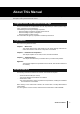
About This Manual This section explains who this manual is aimed at, describes the layout of the manual, and gives a description of the symbols used in this manual. Targeted reader and expected knowledge This manual is written for an administrator who has responsibility for network system configuration, maintenance, and management. Understanding the following knowledge is expected. • Basic knowledge of networks, intranets and the internet. • Basic knowledge of system management.
Symbols used in this manual This manual uses the following symbols. Attention This symbol indicates a point that operator should pay attention to. This symbol indicates supplemental information. Note Refer WARNING CAUTION This symbol indicates a section which describes related information. This symbol means "Danger! You are in a situation that could result in bodily injury". Before continuing, make yourself aware of the hazards involved and become familiar with common ways of preventing accidents.
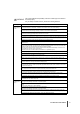
Contents Preface .........................................................................................................1 For Safe Use of the XG700 ..........................................................................2 Warning notations .............................................................................................. 2 No self maintenance .......................................................................................... 5 Warning label ............................................
Appendix ............................................................................................. 35 Appendix-A Specifications ...................................................................................36 A.1 A.2 10 Contents Product Specifications ................................................................................ 36 Installation Specifications ...........................................................................
Installation This chapter lists the items that should be in the XG700 package, describes the names and functions of the various components of the XG700. 1 1-1 Parts List.................................................................................................12 1-2 XG700 Components ...............................................................................14 1-3 Labels .....................................................................................................
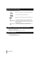
1-1 Parts List Before proceeding, check that all of the following parts were included in your XG700 package. Contact the vendor's service department if any parts are missing and/or the manual has any missing or wrongly collated pages. Keep the hardware guide (this manual) and the CD-ROM in a safe place.
• Rack Mounting Brackets • • • • • • • • • • • • Brackets for mounting the XG700 in a rack. Attach each rack mounting bracket to the right and left sides of the XG700, and fasten to the rack posts with the rack screws (large). Rack Mounting Bracket BR A bracket for mounting the XG700 in a rack. Attach the rack mounting bracket BR to the back-right side of the XG700, and fasten to the rail (attached to the back-right rack post) with the rack screws (small).
1-2 XG700 Components This section explains the names and functions of the various XG700 components, including the various indicator LEDs. XG700 front The following explains the names and functions of the components at the front of the XG700.
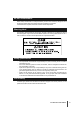
XG700 rear The following explains the names and functions of the components at the rear of the XG700. Rear Fan Unit Power Unit Power Switch Power Unit 1 Power Switch FAN Power Inlet Power Unit LED • Power Switch • Power Supply Unit Power Inlet Rear Fan LED Power Unit LED Used to turn the XG700 on/off. Supplies power to the XG700 (includes an exhaust fan). - Power Supply LED (Green/Orange) Green LED lights when the XG700 is on. Orange LED lights when there is a problem with the Power Supply Unit.
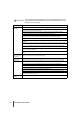
Display LEDs There are three main indicator LEDs on the front of the XG700: Power LED, Alarm LED, and Status LED. The following explains the LED display under various conditions. LED XG700 Condition Power Alarm Status Off Off Off Off Starting up Power just turned on On On Off System starting up On Off *1 Blinking System start-up completed On Off *1 On Operable On Off *1 On After shutdown On Off*1 Off *1: If the XG700 is operating normally.
1-3 Labels A warning sticker, product nameplate, product ID label, and MAC label are to be found in various places on the XG700.
Product nameplate This indicates the model, part number, serial number, etc. Model Part Number Serial Number MODEL. * * * * * * PART NO. PA * * * * * SER NO. P * * * * * * Rev. Label 0 1 2 3 4 5 6 7 8 9 0 1 2 3 4 5 6 7 8 9 0 1 2 3 4 5 6 7 8 9 1 50/60Hz **** Kg 100-240V *** **** A/INPUT PFU Limited a FUJITSU company MADE IN JAPAN Product ID Label This indicates the model and serial number. MODEL ***** SER.
Installation and Operation This chapter explains how the user should proceed from installation to operation of the XG700. 2 2-1 Installation Overview ..............................................................................20 2-2 Installation Procedure .............................................................................21 2-2-1 Installation requirements............................................................21 2-2-2 Installing the XG700 in a rack.........................................
2-1 Installation Overview This section reviews the flow of work as the user proceeds from installation to operation of the XG700. Install the XG700 and the proceed with normal operation as follows: 1 Check the components "1-1 Parts List" 2 Check the set up area and install the XG700 "For Safe Use of the XG700", "2-2 Installation Procedure" 3 Connect the cables to the XG700 Connect the required fiber optic cables and power cords to the XG700.
2-2 Installation Procedure This chapter describes the installation requirements and installation procedure. 2-2-1 Installation requirements Before installing the XG700, read " For Safe Use of the XG700 (P.2)" and comply with the installation requirements described below. Space requirements 2 When installing the XG700, a certain amount of installation space is necessary. When installing the rack, the indicated space (800mm of both the front and rear of the rack) should be reserved as a service area.
Set up requirements Only use the XG700 under the temperature, humidity and other environmental conditions specified in "A.2 Installation Specifications (P.36)". Using the XG700 outside the following ranges can shorten the lifetime or cause the failure of the XG700. Temperature (5 - 40°C) Humidity (20 - 80%RH) When installing the XG700 in a rack, note the following. • Certain types of racks cannot be used. To check whether the XG700 can be installed in a given rack, contact the vendor's service department.
2-2-2 Installing the XG700 in a rack The following explains how to install the XG700 in a 19-inch rack. 1. 2. Take the XG700 out of its box. Fix the cage nuts and rails to the rack posts.
[When the rack has round post holes] Rack Post Rack Screws (Large) Rack Post Rack Nut Rack Screws (Large) Rack Post Rail R Rail L Refer to Detail A Rack Nut Rack Nut Rack Post nt Fro Clip the rack nuts onto the rack post so that the holes are lined up.
3. Fix the four rack mounting brackets to the XG700. Each of the four rack mounting brackets (left, right, back-left, back-right) has three holes that should line up with matching holes on the sides of the XG700, as shown in the diagram. Attach each rack mounting bracket using the countersunk bracket screws provided. Bracket Screws Rack Mounting Bracket BL 2 Bracket Screws Rack Mounting Bracket BR Rack Mounting Bracket Bracket Screws Bracket Screws Rack Mounting Bracket 4.
5. This completes the rack installation procedure. Rack Post Rack Post mp Du Console RS-232 Mng-LAN 1 2 3 4 r we Po rm Ala tus Sta 5 6 7 8 9 10 11 12 2-2-3 Uninstalling the XG700 from a rack The following explains how to uninstall the XG700 from a rack. 1. Undo the rack screws that were used to fasten the XG700 to the rack. Rack Screws (Small) Rack Screws (Small) Rack Screws (Large) Rack Screws (Large) 2. 26 Slide the XG700 forward, and remove it from the rack.
2-3 Cable Connection This section explains how to connect the cables and power cords. 2-3-1 Connecting cables The cables need to be connected to the XG700 Xenpak modules. 1. Connect the cables to the XG700. Connect the cables to the Xenpak modules (Port 1 - Port 12) on the front of XG700.
2-3-2 Connecting the power cords After connecting the peripheral units, connect the XG700 power cords. WARNING • Do not touch the power plug with wet hands, as there is a risk of electric shock. • Do not damage or remodel the power cords, as this may cause electric shock or fire. Placing a heavy object on, pulling, excessively bending, twisting, or overheating a power cord can damage it, and may cause electric shock or fire.
2. Connect the power cord to the power outlet. Insert the plug at the other end of the power cord into the power strip or wall socket. WARNING • Unplug the XG700 during thunder-storms. Continued use under these conditions risks lightning damage to the XG700, and may cause a fire. • When you remove a power plug from its outlet, be sure to pull the only power plug itself. Pulling on the power cord itself may expose the cores or break the cord, and cause electric shock or fire.
2-4 Basic Operation This section explains the basic operation of XG700. 2-4-1 Turning the XG700 on CAUTION Do not move, shock, or vibrate the XG700 while it is on. 1. Turn the power switch to the "on" position by pressing the [ ] side. The Power LED (Green) on the front of the XG700 should turn on. The Alarm LED (Orange) should turn on for a moment, then should turn off. The Status LED (Green) should turn on. If an error occurs while the XG700 is starting up, the Alarm LED (Orange) will start blinking.
Troubleshooting This chapter describes what you should do when your XG700 has problems. 3 3-1 Start-up Problems...................................................................................32 3-2 Hardware Problems................................................................................
3-1 Start-up Problems The following errors may occurs when the XG700 is started up. If the cause of the error cannot be resolved, contact the vendor's service department. The following explains some general errors that can occur. Check if any of these match your problem. The XG700 does not turn on [Symptom] The power switch is turned on, but the XG700 does not power up.
3-2 Hardware Problems This section explains what should be done when a fan, temperature, power supply, or memory error occurs. Contact the vendor's service department when the following errors occurred. Fan error When a problem is detected with a fan, the front panel Alarm LED lights up in orange, the LED of the fan unit in which the error has occurred lights up in orange, and an error is recorded in the event log. If a fan error occurs, contact the vendor's service department.
34 Troubleshooting
Appendix This appendix explains XG700 specifications. Appendix-A Specifications ............................................................................36 A.1 Product Specifications ..................................................................36 A.2 Installation Specifications..............................................................
Appendix-A Specifications This section details the specifications of XG700. A.1 Product Specifications The product specifications of the XG700 are as follows: Items 10 Gigabit ports Overview Port1 - Port12 Serial Port IEEE802.3ak compliant 10 Gigabit Ethernet port X 12 RS-232C D-SUB9 X 1 Console connection port Management LAN Mng-LAN 10BASE-T/100BASE-TX X 1 Indicators LED Power (Green), Alarm (Orange), Status (Green), Rear fan, Power supply units A.
XG700 Hardware Guide P3N1-E041-01EN Date of issue: September 2005 Issuing authority: PFU LIMITED Printed in Japan • Contents of this manual are not to be reproduced without permission from PFU. • The contents of this manual may be updated without notice. • PFU assumes no liability for damages to third party copyrights or other rights arising from the use of any information in this manual. • Manuals with missing or wrongly collated pages will be replaced free of charge.