SPARC Enterprise M4000/M5000 Servers Installation Guide Part No.
Copyright © 2007, 2010, Oracle and/or its affiliates. All rights reserved. FUJITSU LIMITED provided technical input and review on portions of this material. Oracle and/or its affiliates and Fujitsu Limited each own or control intellectual property rights relating to products and technology described in this document, and such products, technology and this document are protected by copyright laws, patents, and other intellectual property laws and international treaties.
Copyright © 2007, 2010, Oracle et/ou ses sociétés affiliées. Tous droits réservés. FUJITSU LIMITED a fourni et vérifié des données techniques de certaines parties de ce composant. Oracle et/ou ses sociétés affiliées et Fujitsu Limited détiennent et contrôlent chacune des droits de propriété intellectuelle relatifs aux produits et technologies décrits dans ce document.
Contents Preface 1. Installation Overview 1.1 2. ix Installation Workflow 1–1 Preparing to Install the Server 2–1 2.1 Safety Precautions 2.2 Before Installing the Server 2.2.1 2.3 3. 1–1 2–1 Facility Power 2–2 2–2 2.2.1.1 Facility Power Requirements and Characteristics 2.2.1.2 Grounding 2–7 2.2.2 Cable Connections 2.2.3 Checking the Installation Location Tools and Equipment Installing the Server 2–4 2–8 2–8 2–9 3–1 3.1 Checking Components 3–1 3.
3.3 3.4 3.5 4. Connecting the Administration Console 3.3.1 Connecting the Console 3.3.2 Initializing the XSCF Unit Powering On the Server 3–7 3–9 3–10 3.4.1 Verifying the Configuration 3.4.2 Checking the Dual-Power Feed 3–11 3–15 Connecting Additional Peripheral Devices Connecting the Domains to the Network 3–15 4–1 4.1 Overview of Network Configuration 4.2 Connecting to the Network 4.3 Verifying the Network Connection 4.4 Verifying Operation by Running Oracle VTS Software A.
B.2.6 B.3 Using the fmstat Command B–8 Traditional Oracle Solaris Diagnostic Commands B.3.1 Using the iostat Command B.3.1.1 B.3.2 Options B–17 B–17 Using the ps Command B.3.6.1 B.3.7 Options B–18 B–18 Using the prstat Command B.3.7.1 Options B–16 B–16 Using the ping Command B.3.5.1 B.3.6 Options B–14 B–14 Using the netstat Command B.3.4.1 B.3.5 Options B–11 B–11 Using the prtconf Command B.3.3.1 B.3.4 Options B–9 B–9 Using the prtdiag Command B.3.2.1 B.3.
viii SPARC Enterprise M4000/M5000 Servers Installation Guide • December 2010
Preface This installation guide describes how to install and set up the SPARC Enterprise M4000/M5000 servers from Oracle and Fujitsu. This document is intended for authorized service providers. References herein to the M4000 server or M5000 server are references to the SPARC Enterprise M4000 or SPARC Enterprise M5000 server.
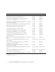
Book Titles Sun/Oracle Fujitsu SPARC Enterprise M4000/M5000 Servers Site Planning Guide 819-2205 C120-H015 SPARC Enterprise Equipment Rack Mounting Guide 819-5367 C120-H016 SPARC Enterprise M4000/M5000 Servers Getting Started Guide* 821-3045 C120-E345 SPARC Enterprise M4000/M5000 Servers Overview Guide 819-2204 C120-E346 SPARC Enterprise M3000/M4000/M5000/M8000/M9000 Servers Important Legal and Safety Information 821-2098 C120-E633 SPARC Enterprise M4000/M5000 Servers Safety and Compliance
Text Conventions This manual uses the following fonts and symbols to express specific types of information. Fonts/symbols Meaning Example AaBbCc123 What you type, when contrasted with on-screen computer output. This font represents the example of command input in the frame. XSCF> adduser jsmith AaBbCc123 The names of commands, files, and directories; on-screen computer output. This font represents the example of command input in the frame.
Documentation Feedback If you have any comments or requests regarding this document, go to the following web sites. ■ For Oracle users: http://docs.sun.com ■ For Fujitsu users in U.S.A., Canada, and Mexico: http://www.computers.us.fujitsu.com/www/support_servers.shtml?s upport/servers ■ For Fujitsu users in other countries, refer to this SPARC Enterprise contact: http://www.fujitsu.com/global/contact/computing/sparce_index.
CHAPTER 1 Installation Overview This chapter provides the process for installing the servers. 1.1 Installation Workflow Installing a server requires the steps in FIGURE 1-1.
FIGURE 1-1 Workflow Required for Installation Preparation Checking the cables and environmental conditions.
CHAPTER 2 Preparing to Install the Server This chapter describes the items you are required to check, the environmental requirements for installation, installation areas, and other related matters. It contains the following sections: 2.1 ■ Section 2.1, “Safety Precautions” on page 2-1 ■ Section 2.2, “Before Installing the Server” on page 2-2 ■ Section 2.
2.2 ■ Be careful not to allow the ambient temperature to rise sharply in winter. Such a sudden temperature change would cause condensation to form inside the product. Allow for a sufficient warm-up period prior to operation. ■ Do not install the server near a copy machine, air conditioner, welding machine, or any other loud equipment. ■ Do not install the server near any equipment generating lots of electronic noise.
TABLE 2-1 Electrical Specifications for the M4000 Server Parameter Value Number of power cords 2 (1 power cord per power supply unit) Redundancy 1 + 1 redundant. Second power supply is redundant at 200 VAC Input current Voltage range 100–127 VAC 200–240 VAC Current, maximum 24.0A at 100–127 VAC (12A per cord) 12.
2.2.1.1 Facility Power Requirements and Characteristics For proper redundancy your facility should have two independent power sources: Either circuit breakers connected to separate power company utility feeds or UPS (uninterruptible power system). For power redundancy the power cords should not be connected to the same facility power source.
FIGURE 2-2 #3 M5000 Server With Redundant PSU Connection #2 #1 #0 PSU#0 PSU#1 PSU#2PSU#3 Circuit breaker Chapter 2 Preparing to Install the Server 2-5
For a dual-power feed connection, connect the individual power cords separately to each AC power supply system.
FIGURE 2-4 #3 M5000 Server With Dual-power Feed Connection #2 #1 #0 PSU#0 PSU#1 PSU#2PSU#3 Circuit breaker Circuit breaker 2.2.1.2 Grounding The system is shipped with grounding-type (three-wire) power cords. Always connect the cords into grounded power outlets. Contact your facilities manager or a qualified electrician to determine what type of power is supplied to your building. No additional earth grounding is necessary but it may be added if desired.
2.2.2 Cable Connections TABLE 2-3 lists the powercords for the servers.
2.3 Tools and Equipment The following sections list the tools that are required to install the servers. The following tools are required to install the servers: ■ Screwdriver, Phillips No.
2-10 SPARC Enterprise M4000/M5000 Servers Installation Guide • December 2010
CHAPTER 3 Installing the Server This chapter describes how to install the server. It contains the following sections: ■ Section 3.1, “Checking Components” on page 3-1 ■ Section 3.2, “Connecting Input Power Cords” on page 3-2 ■ Section 3.3, “Connecting the Administration Console” on page 3-5 ■ Section 3.4, “Powering On the Server” on page 3-10 ■ Section 3.
2. Check for a model name and input format on the shipping list. If any of the items on the packing list are missing, incorrect, or damaged, contact your sales representative. 3.2 Connecting Input Power Cords The servers are shipped with grounding-type (three-wire) power cords. Always connect the cords into grounded power outlets. Caution – The server is designed to work with power systems having a grounded neutral conductor. Do not connect the equipment into any other type of power system.
3.2.1 Connecting a UPS Unit An uninterruptible power supply (UPS) unit is used to provide a stable supply of power to the system in the event of a power failure or an extensive power interruption. A UPS with an UPC interface can be connected to the UPC ports on the eXtended System Control facility unit (XSCFU or XSCF Unit) (FIGURE 3-2) so that emergency shutdown processing can be executed. When using a single power feed, connect the UPC cable to UPC#0.
FIGURE 3-1 M5000 Server Dual-power Feed UPC Connections UPC#1 UPC Interface Cables UPC#0 #3 #2 #1 #0 AC#0 UPC#0 Circuit breaker AC#1 UPC#1 Circuit breaker 3.2.2 Verifying the Power Input Connections Before Applying Power ● Have the site electrician verify that the input power source fulfills the power requirements. Refer to the SPARC Enterprise M4000/M5000 Servers Site Planning Guide for input power requirements.
3.3 Connecting the Administration Console The serial port on the XSCF Unit is a RJ-45 interface port used to monitor the boot process and to modify the default settings. The port is monitored and configured using an administrative console connected to the serial port by a serial cable.
FIGURE 3-2 Ports on XSCF Unit (M5000 Server Shown) 1 2 3 4 5 6 7 3-6 Location Number Component 1 RCI Port 2 Serial Port 3 USB port 4 LAN 1 (Ethernet#1) SPARC Enterprise M4000/M5000 Servers Installation Guide • December 2010
Location Number Component 5 LAN 0 (Ethernet#0) 6 UPC#1 7 UPC#0 See Section A.1, “M4000 Server Views” on page A-1 for the location of the XSCF Unit on the SPARC Enterprise M4000 server. 3.3.1 Connecting the Console This section explains how to physically connect and configure the console. 1. Connect the administrative console to the serial port using the serial cable that shipped with the server. 2. Configure the settings on the administrative console.
FIGURE 3-3 Operator Panel Mode Switch For more details on the operator panel see Section A.3, “Operator Panel Overview” on page A-9. 4. Turn on the input power. Note – Wait at least 30 seconds before turning on the system power that you turned off, by pulling out the power cord or using the circuit breakers on the distribution panel. Refer to the manual that shipped with the input power source for instructions. 5. Watch the administration console for error messages as the XSCF Unit powers on.
Note – If Step 10 is not performed within 1 minute the login certification will expire. 11. Confirm that the XSCF Shell prompt is displayed on the administration console. XSCF> 3.3.2 Initializing the XSCF Unit To use full XSCF functionality, various settings need to be set. 1. Set the required settings. See section “Setting up XSCF” in the SPARC Enterprise M3000/M4000/M5000/M8000/M9000 Servers XSCF User’s Guide for details on how to set these settings.
Note – setdualpowerfeed requires a complete chassis power cycle (all power cords removed) to apply any changes. Make certain to allow 30 seconds before plugging the power cords back into the chassis. To perform XSCF initial settings, use the XSCF default user account. Until user accounts for user environment is registered, log in with a default user account and default password. The privileges of the default user are useradm and platadm. 2.
6. Confirm that the POWER LED (green) on the operator panel is lit. 7. Check the POWER LED on each component. If the POWER LEDs are not lit see Appendix B for installation troubleshooting information. 8. Press and hold the Enter key, and press the “#.” (shift-3 and period) keys. These key combinations switch you from the domain console to the XSCF console. 9. Execute fmdump or showlogs with the error option from the XSCF Shell and confirm that no errors are found. See the Section B.2.
2. Type the showhardconf command with the -u option from the XSCF Shell. XSCF> showhardconf -u SPARC Enterprise M5000; Memory_Size:64 GB; +-----------------------------------+------------+ | FRU | Quantity | +-----------------------------------+------------+ | MBU_B | 1 | | CPUM | 4 | | Freq:2.
4. From the ok prompt, use the probe-scsi-all command to confirm that the storage devices are installed. ok probe-scsi-all /pci@0,600000/pci@0/pci@8/pci@0/scsi@1 MPT Version 1.05, Firmware Version 1.07.00.
The show-devs command command output continued..
3.4.2 Checking the Dual-Power Feed If the dual-power feed option is used, follow the procedure below to confirm that the system can operate even if one power feed is stopped. Note – Dual-Power Feed mode cannot be used with 100V power. 1. Confirm that the system is powered on. 2. Switch off all main line switches of AC GRID A. 3. Confirm that the POWER LED on the operator panel is on. 4. At the XSCF Shell, verify power failure with the showlogs event command. 5.
3-16 SPARC Enterprise M4000/M5000 Servers Installation Guide • December 2010
CHAPTER 4 Connecting the Domains to the Network This chapter discusses how to establish a network for the servers. It contains the following sections: 4.1 ■ Section 4.1, “Overview of Network Configuration” on page 4-1 ■ Section 4.2, “Connecting to the Network” on page 4-1 ■ Section 4.3, “Verifying the Network Connection” on page 4-2 ■ Section 4.
● Connect the network to the domains using an Ethernet cable. You can connect to either the Gigabit Ethernet (GbE) port on the I/O unit or on an Ethernet card installed in the I/O unit. 4.3 Verifying the Network Connection 1. Check the LAN link lamp on the I/O Unit or PCI slot that is connected to the network for activity. 2. Use a system on the network to navigate to one of the domains on the server.
APPENDIX A System Views Appendix A provides views of the systems. This appendix has the following sections: A.1 ■ Section A.1, “M4000 Server Views” on page A-1 ■ Section A.2, “M5000 Server Views” on page A-5 ■ Section A.
FIGURE A-1 M4000 Server Component Locations 41 40 39 38 1 2 3 37 36 35 34 4 5 6 7 8 9 10 33 32 35 31 30 29 28 11 12 27 13 14 26 15 25 24 23 22 21 16 17 A-2 18 19 20 SPARC Enterprise M4000/M5000 Servers Installation Guide • December 2010
Location Number Component 1 60-mm fan (FAN_B#0) 2 60-mm fan (FAN_B#1) 3 Top cover 4 Fan cover 5 Backplane Unit (BPU_A - includes IOBP, Power distribution board) 6 172-mm fan backplane (FANBP_A) 7 60-mm fan backplane (FANBP_B) 8 Tape drive backplane (TAPEBP) 9 Hard disk drive backplane (HDDBP#0) 10 CD-RW/DVD-RW backplane (DVDBP_A) 11 CD-RW/DVD-RW drive unit (DVDU) 12 Hard disk drive (HDD#1) 13 Hard disk drive (HDD#0) 14 Tape drive unit (TAPEU)* 15 Faceplate 16 Power supply un
Location Number Component 30 Memory board (MEMB#1) 31 Memory board (MEMB#0) 32 PCI slot (IOU#0 PCI#0) 33 PCI slot (IOU#0 PCI#1) 34 PCI slot (IOU#0 PCI#2) 35 PCI slot (IOU#0 PCI#3) 36 PCI slot (IOU#0 PCI#4) 37 eXtended System Control facility unit (XSCFU) 38 I/O Unit (IOU#0) 39 DC-DC Converter Riser (DDCR IOU#0 Not shown) 40 DC-DC Converter (DDC_B on DDCR on IOU#0) 41 DC-DC Converter (DDC_A IOU#0 Not shown) * Contact your sales representative for tape drive unit options on M4000/M50
A.2 M5000 Server Views FIGURE A-2 shows the M5000 server.
FIGURE A-2 M5000 Server Component Locations 62 61 60 59 58 1 57 56 55 54 2 53 3 4 52 5 51 50 49 48 6 7 8 9 10 11 12 13 14 15 47 46 45 44 43 42 41 40 39 38 37 36 16 17 18 19 20 21 22 A-6 23 24 25 26 27 28 29 30 31 32 33 34 35 SPARC Enterprise M4000/M5000 Servers Installation Guide • December 2010
Location Number Component 1 Top cover 2 CPU module (CPUM#0) 3 CPU module (CPUM#1) 4 CPU module (CPUM#2) 5 CPU module (CPUM#3) 6 172-mm fan (FAN_A#1) 7 172-mm fan (FAN_A#0) 8 172-mm fan (FAN_A#3) 9 172-mm fan (FAN_A#2) 10 Backplane unit (BPU_B - includes IOBP, Power distribution board, bus bar) 11 172-mm fan backplane (FANBP_C) 12 CD-RW/DVD-RW backplane (DVDBP_B) 13 Tape drive backplane (TAPEBP) 14 Hard disk drive backplane (HDDBP#1 IOU#1) 15 Hard disk drive backplane (HDDBP#0
A-8 Location Number Component 29 DC-DC Converter Riser (DDCR IOU#0 Not shown) 30 DC-DC Converter (DDC_B on DDCR on IOU#0) 31 DC-DC Converter (DDC_A IOU#0 Not shown) 32 I/O Unit (IOU#1) 33 DC-DC Converter Riser (DDCR IOU#1 Not shown) 34 DC-DC Converter (DDC_B on DDCR on IOU#1) 35 DC-DC Converter (DDC_A IOU#1 Not shown) 36 PCI slot (PCI#0 IOU#1) 37 PCI slot (PCI#1 IOU#1) 38 PCI slot (PCI#2 IOU#1) 39 PCI slot (PCI#3 IOU#1) 40 PCI slot (PCI#4 IOU#1) 41 PCI slot (PCI#4 IOU#0) 42 PCI
Location Number Component 59 Memory Board (MEMB#3) 60 Memory board (MEMB#2) 61 Memory board (MEMB#1) 62 Memory board (MEMB#0) * Contact your sales representative for tape drive unit options on M4000/M5000 servers. A.3 Operator Panel Overview When no network connection is available the operator panel is used to start or stop the system. The operator panel displays three LED status indicators, a power switch, and a security keyswitch.
FIGURE A-3 M4000 Server Operator Panel 1 2 3 4 5 6 Location Number Component 1 POWER LED 2 XSCF STANDBY LED 3 CHECK LED 4 Power switch 5 Mode switch (keyswitch) 6 Antistatic ground socket FIGURE A-4 shows the M5000 server operator panel.
FIGURE A-4 M5000 Server Operator Panel 1 2 3 4 5 6 Location Number Component 1 POWER LED 2 XSCF STANDBY LED 3 CHECK LED 4 Power switch 5 Mode switch (keyswitch) 6 Antistatic ground socket Appendix A System Views A-11
During startup, the firmware toggles the front panel LEDs on and off to verify that each one is working correctly. After that, the front panel LEDs operate as described in TABLE A-1. TABLE A-1 Icon Operator Panel LEDs and Switches Name Color Description Green Indicates the server power status. • On: Server has power. • Off: Server is without power. • Blinking: The power-off sequence is in progress. XSCF STANDBY LED Green Indicates the readiness of the XSCF. • On: XSCF unit is functioning normally.
The following table provides the meanings of the mode switch. TABLE A-2 Meanings of the Mode Switch Function Mode Switch State Definition Locked Service Inhibition of Break Signal Reception Enabled. Reception of the break signal can be enabled or disabled for each domain using setdomainmode.
A-14 SPARC Enterprise M4000/M5000 Servers Installation Guide • December 2010
APPENDIX B Fault Isolation This chapter describes basic fault isolation information related to installation of the SPARC Enterprise M4000/M5000 servers from Oracle and Fujitsu. This appendix has the following sections: B.1 ■ Section B.1, “Corrective Actions to Common Problems” on page B-1 ■ Section B.2, “Using the Diagnostic Commands” on page B-2 ■ Section B.
■ Refer to the SPARC Enterprise M4000/M5000 Servers Service Manual for LED status. TABLE B-2 B.2 Types of Troubleshooting Methods Troubleshooting Method Description Check LEDs The system LEDs (on the operator panel) indicate any system or hardware error detected during initial diagnosis or system operation. Additional LEDs are provided on the XSCF Unit, power supply unit, fan unit, and other units so that you can always locate faulty components and identify specific errors.
An example of the showhardconf output. .
showhardconf output continued.
B.2.2 Using the showlogs Command The showlogs command displays the contents of a specified log in order of timestamp starting with the oldest date. The showlogs command displays the following logs: ■ error log ■ power log ■ event log ■ temperature and humidity record ■ monitoring message log ■ console message log ■ panic message log ■ IPL message log An example of the showlogs output.
B.2.3 Using the showstatus Command The showstatus displays the information concerning the server’s degraded FRUs. An asterisk (*) which indicates that the unit has been degraded is displayed along with any of the following states: ■ Normal ■ Faulted ■ Degraded ■ Deconfigured ■ Maintenance An example of the showstatus output. XSCF> showstatus FANBP_C Status:Normal; * FAN_A#0 Status:Faulted; XSCF> B.2.
At least three lines of new output are delivered to the user with the -V option: B.2.4.2 ■ The first line is a summary of information you have seen before in the console message but includes the timestamp, the UUID, and the Message-ID. ■ The second line is a declaration of the certainty of the diagnosis. In this case you are 100 percent sure the failure is in the asic described.
B.2.5.1 fmadm config Command The fmadm config command output shows the version numbers of the diagnosis engines in use by your server, as well as their current state. You can check these versions against information on the My Oracle Support website to determine if you are running the latest diagnostic engines. An example of the fmadm output. XSCF> fmadm config MODULE eft event-transport faultevent-post fmd-self-diagnosis iox_agent reagent sysevent-transport syslog-msgs XSCF> B.2.6 VERSION 1.16 2.0 1.
B.3 Traditional Oracle Solaris Diagnostic Commands These superuser commands can help you determine if you have issues in your server, in the network, or within another server that you are networking with. The following commands are detailed in this section. ■ Section B.3.1, “Using the iostat Command” on page B-9 ■ Section B.3.2, “Using the prtdiag Command” on page B-11 ■ Section B.3.3, “Using the prtconf Command” on page B-14 ■ Section B.3.4, “Using the netstat Command” on page B-16 ■ Section B.3.
TABLE B-3 Options for iostat (Continued) Option Description How It Can Help -e Displays device error summary statistics. The total Provides a short table with accumulated errors, hard errors, soft errors, and transport errors errors. Identifies suspect I/O devices. are displayed. -E Displays all device error statistics. Provides information about devices: manufacturer, model number, serial number, size, and errors. -n Displays names in descriptive format.
B.3.2 Using the prtdiag Command The prtdiag command displays configuration and diagnostic information. The diagnostic information identifies any failed component. The prtdiag command is located in the /usr/platform/platform-name/sbin/ directory. Note – The prtdiag command might indicate a slot number different than that identified elsewhere in this document. This is normal. B.3.2.1 Options TABLE B-4 describes options for the prtdiag command and how those options can help troubleshooting.
The following example shows output for the prtdiag command in verbose mode.
prtdiag -v output continued.
B.3.3 Using the prtconf Command Similar to the show-devs command run at the ok prompt, the prtconf command displays the devices that are configured. The prtconf command identifies hardware that is recognized by the Oracle Solaris OS. If hardware is not suspected of being bad yet software applications are having trouble with the hardware, the prtconf command can indicate if the Oracle Solaris software recognizes the hardware, and if a driver for the hardware is loaded. B.3.3.
The following example shows output for the prtconf command.
B.3.4 Using the netstat Command The netstat command displays the network status. B.3.4.1 Options TABLE B-6 describes options for the netstat command and how those options can help troubleshooting. TABLE B-6 Options for netstat Option Description How It Can Help -i Displays the interface state, including packets in/out, error in/out, collisions, and queue. Provides a quick overview of the network status.
B.3.5 Using the ping Command The ping command sends ICMP ECHO_REQUEST packets to network hosts. Depending on how the ping command is configured, the output displayed can identify troublesome network links or nodes. The destination host is specified in the variable hostname. B.3.5.1 Options TABLE B-7 describes options for the ping command and how those options can help troubleshooting.
The following example shows output for the ping -s command. # ping -s san-ff2-17-a PING san-ff2-17-a: 56 data bytes 64 bytes from san-ff2-17-a (10.1.67.31): icmp_seq=0. time=0.427 ms 64 bytes from san-ff2-17-a (10.1.67.31): icmp_seq=1. time=0.194 ms ^C ----san-ff2-17-a PING Statistics---2 packets transmitted, 2 packets received, 0% packet loss round-trip (ms) min/avg/max/stddev = 0.172/0.256/0.427/0.102 # B.3.6 Using the ps Command The ps command lists the status of processes.
# ps PID TTY 101042 pts/3 101025 pts/3 # TIME CMD 0:00 ps 0:00 sh Note – When using sort with the -r option, the column headings are printed so that the value in the first column is equal to zero. B.3.7 Using the prstat Command The prstat utility iteratively examines all active processes and reports statistics based on the selected output mode and sort order. The prstat command provides output similar to the ps command.
B.3.7.1 Options TABLE B-9 describes options for the prstat command and how those options can help troubleshooting. TABLE B-9 Options for prstat Option Description How It Can Help No option Displays a sorted list of the top processes that are consuming the most CPU resources. List is limited to the height of the terminal window and the total number of processes. Output is automatically updated every five seconds. Ctrl-C aborts.