ServerView Resource Orchestrator Cloud Edition V3.1.
Preface Resource Orchestrator Documentation Road Map The documentation road map for Resource Orchestrator is as shown below. Resource Orchestrator Documentation Road Map Point Refer to the user role manuals displayed in the table below for roles that are not in the diagram.
Purpose This manual provides an outline of ServerView Resource Orchestrator (hereinafter Resource Orchestrator) and the operations and settings required for setup. Target Readers This document is intended for Infrastructure Administrator who display L-Platforms, manage tenant information, or use the dashboard or operation status to monitor resources. It is assumed that these users have a general knowledge of server virtualization software products and directory services such as Active Directory and LDAP.
Appendix C Tenant Operation by Dual-Role Administrators Explains tenant operation by dual-role administrators Glossary Explains the terms used in this manual. Please refer to it when necessary. Notational Conventions The notation in this manual conforms to the following conventions.
- The URLs in this manual were correct when the manual was written. Menus in the ROR console Operations on the ROR console can be performed using either the menu bar or pop-up menus. By convention, procedures described in this manual only refer to pop-up menus. Regarding Installation Folder Paths The installation folder path may be given as C:\Fujitsu\ROR in this manual. Replace it as shown below.
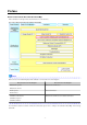
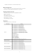
Abbreviation Products Windows Server 2003 Microsoft(R) Windows Server(R) 2003 R2, Standard Edition Microsoft(R) Windows Server(R) 2003 R2, Enterprise Edition Microsoft(R) Windows Server(R) 2003 R2, Standard x64 Edition Microsoft(R) Windows Server(R) 2003 R2, Enterprise x64 Edition Windows 2003 x64 Edition Microsoft(R) Windows Server(R) 2003 R2, Standard x64 Edition Microsoft(R) Windows Server(R) 2003 R2, Enterprise x64 Edition Windows 8 Windows(R) 8 Pro Windows(R) 8 Enterprise Windows 7 Windows(R)
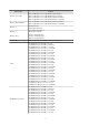
Abbreviation Products Red Hat(R) Enterprise Linux(R) 5.7 (for Intel64) Red Hat(R) Enterprise Linux(R) 5.8 (for x86) Red Hat(R) Enterprise Linux(R) 5.8 (for Intel64) Red Hat(R) Enterprise Linux(R) 6.2 (for x86) Red Hat(R) Enterprise Linux(R) 6.2 (for Intel64) Red Hat(R) Enterprise Linux(R) 6.3 (for x86) Red Hat(R) Enterprise Linux(R) 6.3 (for Intel64) Red Hat Enterprise Linux 5 Red Hat(R) Enterprise Linux(R) 5 (for x86) Red Hat(R) Enterprise Linux(R) 5 (for Intel64) Red Hat(R) Enterprise Linux(R) 5.
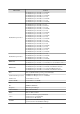
Abbreviation Products VMware VMware vSphere(R) 4 VMware vSphere(R) 4.1 VMware vSphere(R) 5 VMware vSphere(R) 5.1 VMware ESX VMware(R) ESX(R) VMware ESX 4 VMware(R) ESX(R) 4 VMware ESXi VMware(R) ESXi(TM) VMware ESXi 5.0 VMware(R) ESXi(TM) 5.0 VMware Tools VMware(R) Tools VMware vSphere 4.0 VMware vSphere(R) 4.0 VMware vSphere 4.1 VMware vSphere(R) 4.1 VMware vSphere 5 VMware vSphere(R) 5 VMware vSphere 5.1 VMware vSphere(R) 5.
Trademark Information - BMC, BMC Software, and the BMC Software logo are the exclusive properties of BMC Software, Inc., are registered with the U.S. Patent and Trademark Office, and may be registered or pending registration in other countries. - EMC, EMC2, CLARiiON, Symmetrix, and Navisphere are trademarks or registered trademarks of EMC Corporation. - HP is a registered trademark of Hewlett-Packard Company.
Contents Chapter 1 Overview..................................................................................................................................................................1 1.1 Function List........................................................................................................................................................................................1 1.2 Flow of Operations................................................................................................
8.2.3.2 Segment Tab........................................................................................................................................................................74 8.2.3.3 Image Tab............................................................................................................................................................................76 8.2.3.4 Software Tab..............................................................................................................
Chapter 13 Account..............................................................................................................................................................142 13.1 Referencing User Information.......................................................................................................................................................142 13.2 Changing User Information..................................................................................................................
Chapter 1 Overview This chapter explains the ROR Console. 1.1 Function List This section explains the functions provided by ROR Console. ROR Console has two parts: "operation windows for tenant administrators and tenant users" and "operation windows for infrastructure administrators". Windows intended for Tenant Administrators and tenant users are provided for L-Platform and user information operations.
Function Overview Infrastructure Administrator Tenant Administrator Tenant user Dashboard (Capacity Planning) Anticipate the demand for resource pools and perform simulations of VM guest reallocations.
Flow from Construction to Operation (Infrastructure Administrator) Construction 1. Registering resources Register resources. Refer to "Chapter 5 Registering Resources" in the "User's Guide for Infrastructure Administrators (Resource Management) CE" for details. 2. Registering network device control scripts Deploy the network device control scripts. Refer to "5.
5. Publishing L-Platform Templates Publish the created L-Platform Template. Refer to "8.3.6 Publishing and Hiding L-Platform Template" for details. 6. Creating tenants, tenant administrators, and tenant users Register the tenant, Tenant Administrator, and tenant users. Refer to "Chapter 11 Tenant" for details. Operation [Assessing Applications from Tenant] 1.
Chapter 2 Login and Logout This chapter describes how to open and close the ROR console. Preparations Before opening the ROR console, be sure to read the following instructions and restrictions. - When accessing the ROR console, be sure to enable the Compatibility View in Internet Explorer. Select [View]-[Encoding] in Internet Explorer, and check if [Auto-Select] is checked. If [Auto-Select] is not checked, select it.
URL: https://Admin_server_FQDN:23461/ On a Windows admin server, the ROR console can also be opened by selecting [start]-[All Programs]-[Resource Orchestrator]-[ROR console]. Note - If the login screen is not displayed, confirm the following. - URL entered in address bar of the Web browser. - The proxy settings of the Web browser are correct. - The firewall settings on the admin server are correct.
Chapter 3 Home This chapter explains the ROR Console Home window. When the ROR Console is started, the Home window is displayed. Refer to "Chapter 2 Login and Logout" for information on how to start the ROR Console. The elements of the Home window are explained below. - Functions list The functions list displays the items that can be operated using ROR Console tabs. Click the triangle icon next to the Function list to toggle Display/Hide.
Note - If the application process checkbox is being changed from on to off after the manager starts its operation, make sure that there are no pending processes before changing it. If there are pending processes, finish all of them by cancelling, approving, rejecting, accepting, or dismissing each of them. - Set the following settings on "L-Platform 1/2" and "L-Platform 2/2" before operations commence. This attribute cannot be switched once operations have commenced.
Step Setting Items Overcommit function Description The L-Platform Management overcommit function can be set. When "Enable" is selected, the definition for displaying the reserved CPU frequency and memory in the System Condition Server List is also made. Neither the number of CPUs nor the memory size set in "Display Function Settings for Estimated Price" and "Usage Charge Calculator Settings", which are settings related to the overcommit function, are set here. Please change the setting if necessary.
Step Step 6 Accounting Setting Items Description Usage fee (estimated price) for L-Platform Tab It is possible to set whether to display the Usage fee (the estimated price) on the L-Platform Tab in the L-Platform Management window based on LPlatform template accounting information. Refer to "8.7.1 Display Function Settings for Estimated Price" in the "Operation Guide CE". Display of the Accounting tab The usage charge calculator function can be set. Refer to "8.7.
"Setup Guide CE" "Chapter 8 Creating Definition Files" 8.1 Definition Files (For Both Physical L-Servers and Virtual L-Servers) 8.2 Definition Files (For Physical L-Servers) 8.3 Definition Files (For Virtual L-Servers) 8.4 Definition Files (Network) "Chapter 18 Post-Installation Procedures" 18.2.1 Registering an Application Process Assessor 18.3 Customizing the Dashboard 18.10 Setting for the Restarting Managers 18.11 Changing Multiple Operations of Managers 18.12 Edit the License Agreement 18.
3. The [Edit - Information] window is displayed. To add information, click [Add] on the [Edit - Information] window. To perform other operations, select information from the list, and then click [Move up]/[Move down], [Edit], or [Delete]. Click [Save] to save the changes after operations have been completed. Adding Information This section explains how to add information. Perform the following procedure to add information. a. Click [Add] on the [Edit - Information] window.
Deleting Information This section explains how to delete information. Perform the following procedure to delete information: a. Select the information to delete from the list. b. Click [Delete]. The [Delete entry] dialog is displayed. c. Click [Yes]. The selected information is deleted. 4. Click [Save] to save the changes after operations have been completed. Click [Cancel] to discard the changes and return to the [Information] window.
Chapter 4 Dashboard (Pool Conditions) This chapter explains how to use pool condition operations. 4.1 Pool Conditions Overview The Pool Conditions can be used to monitor resource pool use. This section provides an overview of the Pool Conditions.
1. From the ROR console, select the Dashboard tab, then select Pool Conditions in the displayed sub tab. Charts are displayed for use rate of each resource pool. Note Dual-role administrator privileges Global pool is displayed by default when logging in as the dual-role administrator. To reference another pool, use the Tenant ID menu at the top right of the window. The following table lists the six types of charts available.
Icon Explanation Displays the relationship chart menu Selects the relationship chart for either "Use state" or "Allocatable L-Servers". Switches between the use rate chart and the relationship chart. Updates the chart with the most recent information Toggles between table and polyline graph displays Displays a list of functions The following functions may be used: - Refresh: Updates the chart to the latest information. - Change table/graph: Switches between the table and the graph.
A window example is shown below. Point When returning to the use rate window from the relationship chart window, click on the icon to move the displayed slider to the top. Note - If the Pool Conditions window is left open in a Web browser, the connection to the server may time-out and an error may display in the window. If this occurs, close the Web browser, and then display the Pool Conditions window again.
4.3 Chart Display This section explains the charts for each resource pool. The resource pool charts display resource pool use rates as polyline graphs for each resource pool. If there are multiple resource pools, the use rates of the display periods of each of the resource pools are added together, and the top five are displayed in order, starting with the one with the highest total. The use rate graph displays the daily average. The displayed data will be updated every five minutes.
Display format Detailed information (Allocatable LServers) (*1) Usage scenario check the number of L-Servers that can be deployed. *1: The relationship chart that displays the number of deployable L-Servers is not displayed for network pools and address pools. LServers can be deployed even if the network pool and address pool are exhausted.
4.4 Alert List Display This section explains the Alert list. If an alert has occurred in a resource pool, detailed information on the alert that has occurred can be checked by the Alert List. The methods of checking detailed information on alerts are the method of displaying all alerts and the method of displaying alerts for each chart. Information Refer to "Appendix E To Customize Dashboard" in the "Setup Guide CE" for information on how to customize alert information. 4.4.
Button Description Refresh Updates the Alert list to the latest status. Comments The Comment dialog box will be displayed. Adds a comment on an alert selected from the Alert list. Allows a history of past comments to be viewed. In addition, changes the status of an alert to "Resolve Alert" in accordance with the addition of the comment. Configure The Alert Configure dialog box will be displayed. Sets the alert display. Modifies search conditions and customizes the display result.
[Alert configuration] dialog box (Custom Columns) Set the contents of the items in the table below that are displayed in the Alert list window. Item Description Auto Refresh Specify the interval at which the window is to be updated. The default is "5". Number of results Specify the number of items to be displayed in the Alert list. Custom Columns Select the items to be displayed in the Alert list from "Available Custom Columns". 4.4.
The table below explains the buttons at the top right of the Alert list window. Button Description Comments The Comment dialog box will be displayed. Adds a comment on an alert selected from the Alert list. Allows a history of past comments to be viewed. In addition, changes the status of an alert to resolve in accordance with the addition of the comment. Print Outputs an image of the Alert list. The table below explains the tab at the bottom of the Alert list window.
Chapter 5 Dashboard (System Conditions) This chapter explains how to monitor system conditions. Note The following message may be displayed during monitoring of system conditions: The authority error occurred. Closing the browser. This error occurs if, for example, the same user ID is used to log in from a different client. In this case, log in again correctly. 5.
- Tenant Displays the L-Platforms and L-Servers currently in use. - Tenant (History) The L-Platforms and L-Servers, including ones used in the past, are displayed. Those that were cancelled over a year ago are no longer displayed in the history. Point The following describes how to find an L-Platform to display when there are a large number of L-Platforms. 1. Select the tenant in the pane on the left.
Item Explanation Configuration Information Display" for the displayed configuration information.
*2: The display interval can be switched to a shorter interval by clicking the data plotting area of a horizontal polyline graph, or switched to a longer interval by clicking outside the data plotting area. *3: Disk usage and network usage are not displayed if the virtualization software is Hyper-V, RHEL5-Xen, and Solaris Zones. *4: The disk R/W count is not displayed if the virtualization software is Hyper-V, RHEL-KVM, and Solaris Zones.
- Total tab - All tab At each tab, the following icons displayed in the title bar can be used: Icon Tool tip Update Explanation Updates the displayed contents - 28 -
Icon Tool tip Explanation Download CSV file Downloads the graph data in CSV format Minimize Minimizes the specified window Maximize Maximizes the specified window Restore Restores the maximized window The table below shows the CSV file items if data is downloaded from each graph. Note that the CSV file encoding is Shift-JIS.
Graph type Disk R/W usage Column name Explanation Unit Description xenpcused CPU utilization % Output only for RHEL5-Xen CPU utilization (total utilization of virtual CPUs set in the domain) xencpun Number of virtual CPUs in the domain number Output only for RHEL5-Xen Nickname VM name kvmcpupcent CPU utilization % Output only for RHEL-KVM CPU utilization (total utilization of virtual CPUs set in the domain) kvmcpus Number of virtual CPUs in the domain zonecpucappct CPU utilization sd
Graph type Disk R/W count Column name Explanation kvmdiskblockwrby Disk write usage sdattim Collection start time (*) Unit bytes Description Output only for RHEL-KVM Disk write usage in the domain yyyy-mm-dd HH:mm:ss - in case of physical servers and Windows: drive name or _Total resrcid Resource ID - in case of physical servers and Linux/ Solaris: device name Output any of the following - WIN_PHYDISKBUSY recid Record ID - UX_DISKBUSY - VMW_DISK - in case of interval time is 10 minutes: 600 c
Graph type Column name Explanation Unit Description - UX_MEMFREE - VMW_MEM - HV_DMEM_VM - XEN_MEM - KVM-MEM - in case of interval time is 10 minutes: 600 consintl Interval time - in case of 1 hour: 3600 - in case of 24 hour: 86400 Network utilization coverage Data coverage (0 to 1) comtot Memory usage bytes Output only for Windows Commit size freememp Memory usage bytes Output only for Linux Memory size utilization for user processes memuse Memory usage percent Output only for Linux
Graph type Column name Explanation Unit Description ifbytin Network usage (received) bytes Output only for Windows Amount of received data(byte) ifbytot Network usage (sent) bytes Output only for Windows Amount of sent data(byte) vmnpmvtr Network usage (sent) Mbits Output only for VMware Amount of data transferred by virtual network device port unit vmnpmbrecv Network usage (received) Mbits Output only for VMware Amount of data received by virtual network device port unit xenkbtx Netwo
The table below explains the displayed items. Item Selected Information Explanation GID Displays the identifier set by the system to identify the configuration item. CI Type Displays the configuration item type. The CI types are as follows: - Tenant: If a tenant is selected - L-Platform: If an L-Platform is selected - L-Server: If an L-Server is selected Nickname Displays the display name of the configuration item.
Item Explanation - If the element is an instance: The value set during L-Platform subscription - If the element is L-Server node information: The value set during LPlatform subscription or L-Platform reconfiguration Basic Information Attribute Displays the attribute name. When the label in the upper part is clicked, items can be sorted by attribute name. Value Displays the attribute value. When the label in the upper part is clicked, items can be sorted by attribute value.
Item Explanation VM Host Displays the VM host name displayed at Resource tab - Trees pain in ROR console display. Note that name change is not always reflected immediately in some cases, for example, when you change the VM host name on the VM Management Software. The change is usually reflected within five minutes. IP Address Displays the IP address of the VM host. Number of VMs Displays the number of the running VM guests that was deployed on the VM host in the L-Platform management page.
*2: The display interval can be switched to a shorter interval by clicking the data plotting area of a horizontal polyline graph, or switched to a longer interval by clicking outside the data plotting area. *3: Will not display if the VM host virtualization software used is either RHEL5-Xen, RHEL-KVM, or Solaris Zones. Note - The system conditions data is not reflected in the display until collection at the fixed intervals shown below is completed. Check the display after the fixed intervals shown below.
- Total tab - All tab At each tab, the following icons displayed in the title bar can be used: Icon Tool tip Explanation Update Updates the displayed contents Download CSV file Downloads the graph data in CSV format Minimize Minimizes the specified window - 38 -
Icon Tool tip Explanation Maximize Maximizes the specified window Restore Restores the maximized window The table below shows the CSV file items if data is downloaded from each graph. Note that the CSV file encoding is Shift-JIS.
4. A list of servers that match the search conditions is displayed. The table below explains the items displayed in the server list. Item Explanation Tenant Name The tenant name of the tenant related to the L-Server Example: First Business Department L-Server Name The server name of the L-Server Example: ID015-WEB-001 Host Name The host name of the L-Server Example: V4KRXZS6R60001 Type The L-Server type Example: economy IP Address IP address of the L-Server control NIC Example: 192.0.2.
Item Explanation Total Added Disk(GB) The total value of the disk size for added disks. If there are multiple added disks, the total value for those disks is output. The unit is GB. Example: 60.0 Note Clicking the server list column headers to sort the columns is effective only for the range displayed in that same page. The sorting specification is reset when the next or previous page is displayed. Sorting spanning multiple pages is not available.
Chapter 6 Dashboard (Capacity Planning) This chapter describes capacity planning operations. Scenarios are prepared in the Capacity Planning window to suit any operational purpose. Analysis and planning are facilitated by checking each report in turn Note If the character " ' " is used in the display name of a tenant, it is displayed as the character "_" on the Capacity Planning window. 6.1 Report Types This section describes the types of reports for each category. Refer to "6.
ServerView Resource Orchestrator Resource pool Reports Reports Display item VM pool(CPU) (demand forecast) VM pool(CPU) (demand forecast) VM pool(Memory) (demand forecast) VM pool(Memory) (demand forecast) Storage pool (demand forecast) Storage pool (demand forecast) Network pool (demand forecast) Network pool (demand forecast) Server pool (demand forecast) Server pool (demand forecast) Address pool (demand forecast) Address pool (demand forecast) Description Perform regression analysis based
Item No. Component Description (1) Conditions window Set categories, reports, and the analysis conditions for the various reports. Operations in this window are described in following sections: (2) Results window The contents of the reports are displayed.
Basic operations in the conditions window Item No. Component Description (1) Category Select a category that matches the purpose of operation. (2) Report Select a report that matches the purpose of operation. (3) Target Settings A specification relating to the target of the report. (4) View Settings Specify report data intervals, number of display items, and file output. The way to specify the number of display items depends on the type of report.
6.2.2 Conditions 6.2.2.1 Target Settings When a report is specified, the following items are displayed: The items displayed are report specific. The following is an example window when Tenant and Host are specified: The items that are specified are explained below for the different types. Tenant specified Item Tenant Description Select the tenant to be analyzed from the tenant menu. Tenant and Host specified Item Description Tenant Select the tenant to be analyzed from the tenant menu.
Item Description Tenant Relocation candidate Select the tenant to be used for VMware virtual machine simulation from the tenant menu. Relocation candidate To add a candidate for reallocation, click Add, then add using the Add Relocation candidate dialog that is displayed. A list of candidates for reallocation is shown when making additions. The display format is "host name:virtual machine name". The maximum number of relocation candidates is 50.
Note Virtual hosts that have been stopped for more than 5 hours do not display virtual machine candidates for reallocation. 6.2.2.2 View Settings The following explains specifications relating to the number of display items, data intervals, and file output: The items to be set differ depending upon the report type. Item Threshold Description Specify the CPU and memory usage rates that will be tolerated on the consolidation destination server (optional).
Item Description If the Creates an Excel(R) file check box is selected, the Save in Excel(R) format button becomes active at the bottom of the results window. Click this button and the displayed content can be downloaded in Excel format. Disable clipboard redirection if operation is to be performed using a remote desktop connection. If downloading files from the Save in Excel(R) format button, the "xlsx" or "xlsm" extension files can be downloaded.
- Address pool (demand forecast) Item Description Date Forecasting is performed up to the specified date. Select the day, month and year using a drop-down list box to select the date. 6.2.4 Operation Buttons (Display) The operation buttons are explained below. Button Description Display Report is created based on the specified conditions. Reports are displayed in the results window. The message "Loading..." is displayed while the content is being generated.
String Description VMW_GCPU CPU usage VMW_MEM Memory usage VMW_DISK Disk I/O count, disk throughput VMW_NET Network send and receive count, network throughput Note The memory usage displayed in the report for the VMware rsc. usage cond.(List of host) in the VMware virtual machine relocation category is the "Total value of memory usage by all currently operating virtual machines and memory usage for vSphere services".
Item Column name consintl Explanation Interval Unit second Description - If collection interval is 10 minutes: 600 - If collection interval is 1 hour: 3600 - If collection interval is 24 hours:86400 CPU(VMW_P CPU2) coverage Data coverage ratio Displays the ratio of data collected during the interval from 0 through 1 vmpcpul CPU utilization sdattim Collection start time sysname System name resrcid Resource ID _Total recid Record ID VMW_PCPU2 consflag Interval (flag displayed) % Avera
Item Column name consflag Explanation Unit Description - If collection interval is 10 minutes: 1 Interval (flag displayed) - If collection interval is 1 hour: 2 - If collection interval is 24 hours: 3 consintl Interval second - If collection interval is 10 minutes: 600 - If collection interval is 1 hour: 3600 - If collection interval is 24 hours:86400 Network (VMW_NET) coverage Data coverage ratio Displays the ratio of data collected during the interval from 0 through 1 vmpdreads Disk readi
Item Column name consintl Explanation Interval Unit second Description - If collection interval is 10 minutes: 600 - If collection interval is 1 hour: 3600 - If collection interval is 24 hours:86400 Hardware resources information (VMW_PME M) coverage Data coverage ratio Displays the ratio of data collected during the interval from 0 through 1 vmpcusemhz CPU usage MHz vmpccorenum CPU core Number number vmpccoremhz CPU speed per core MHz sdattim Collection start time sysname System name
Item Memory Column name Explanation Unit Description vmgcusemhz Virtual machine CPU usage MHz vmname Virtual machine name sdattim Collection start time sysname System name resrcid Resource ID VMware unique ID is specified before the colon, and the virtual machine name is specified after the colon.
Item Column name Explanation resrcid Resource ID recid Record ID consflag Interval (flag displayed) Unit Description VMW_NET - If collection interval is 10 minutes: 1 - If collection interval is 1 hour: 2 - If collection interval is 24 hours: 3 consintl Interval second - If collection interval is 10 minutes: 600 - If collection interval is 1 hour: 3600 - If collection interval is 24 hours:86400 coverage Data coverage ratio Displays the ratio of data collected during the interval from 0 th
Item Column name Explanation Unit Description - If collection interval is 24 hours: 3 consintl Interval second - If collection interval is 10 minutes: 600 - If collection interval is 1 hour: 3600 - If collection interval is 24 hours:86400 Disk coverage Data coverage ratio vmgmtm Estimated size of the working set of a resource pool or a virtual machine sdattim Collection start time sysname System name resrcid Resource ID recid Record ID consflag Interval (flag displayed) Displays the
Item Column name Explanation Unit Description vmnppcktrecv No. of inbound packets packets Physical or virtual network device port units vmnpmbrecv Receive size Mbits Physical or virtual network device port units Note About the data output as CSV At the collection start time, information for the analysis period is output. Data for anticipated periods in the future is not output. 6.2.6.
Item Column name Explanation Unit Description sysname System name resrcid Resource ID VMware unique ID is specified before the colon, and the virtual machine name is specified after the colon.
Column name Explanation Unit Description - If collection interval is 1 hour: 2 - If collection interval is 24 hours: 3 consintl Interval second - If collection interval is 10 minutes: 600 - If collection interval is 1 hour: 3600 - If collection interval is 24 hours:86400 coverage Data coverage ratio Displays the ratio of data collected during the interval from 0 through 1 vmpoolprocused VMPool CPU usage GHz vmpoolproctotal VMPool CPU total size GHz VM pool (Memory) (demand forecast) Column
Column name Explanation Unit Description - If collection interval is 24 hours:86400 coverage Data coverage ratio Displays the ratio of data collected during the interval from 0 through 1 vmpoolserverused StoragePool usage Gbytes vmpoolservertotal StoragePool total capacity Gbytes Network pool (demand forecast) Column name Explanation Unit Description sdattim Collection start time sysname System name resrcid Resource ID tenanl name:/pool name recid Record ID ROR_NETWORKPOOL consfla
Column name Explanation Unit vmpoolserverused Number of servers used by ServerPool number vmpoolservertotal Total number of ServerPool servers number Description Address pool (demand forecast) Column name Explanation Unit Description sdattim Collection start time sysname System name resrcid Resource ID tenanl name:/pool name recid Record ID ROR_ADDRESSPOOL consflag Interval (flag displayed) yyyy/mm/dd HH:mm:ss - If collection interval is 10 minutes: 1 - If collection interval is 1
This section describes the procedure for simulating using a [VMware virtual machine reallocation] category scenario. Understanding the current status In the Capacity Planning window, select the VMware rsc. usage cond. (List of host) report of the VMware virtual machine relocation category, set the analysis conditions and display the report. Refer to "6.2 Capacity Planning Operations" for information on how to configure analysis conditions.
A list of resources allocated to each host and resource usage is displayed. Sort by CPU usage and memory usage where overcommit is enabled to check which hosts have available resources. For example, consider the host with the lowest amount of resource usage as the migration source, and the host with the next lowest rate as the migration target. Also check the hosts that are being considered as a migration source and target to see whether the disk and network throughput is acceptable.
- 65 -
The resource usage information for all virtual machines on the migration source host are displayed in a stack graph. Check the resource usage in each virtual machine, and use this information to ascertain which virtual machine should go to which destination candidate host. Simulation of reallocation In the Capacity Planning window, select the VMware virtual machine relocation simulation report of the VMware virtual machine relocation category, set the analysis conditions and run the simulation.
- Weekly display - Time-line display The information about virtual machines to be consolidated and all virtual machines in the consolidation destination are displayed in a stack graph. Tables are also displayed along with the above graphs. If a value will be too great throughout a period of time or there is a bias for certain time slots or days of the week, consider the combinations of the virtual machines to be reallocated. If a tolerated threshold value was set, check that the value is not exceeded. 6.
This section describes the procedure for attempting to optimize resource by using the VMware resource allocation optimization category scenario. Understanding the current status In the Capacity Planning window, select the VMware rsc. usage cond. (List of virtual machine) report of the VMware resource allocation optimization category, set the analysis conditions and display the report. Refer to "6.2 Capacity Planning Operations" for information on how to configure analysis conditions.
6.3.3 Anticipating the Future Demand for Resources : [ServerView Resource Orchestrator Resource pool] Use the past resource pool usage to anticipate the demand for resource pools. By determining inadequate resource amounts beforehand, it is possible to plan for the expansion of facilities. This section describes the procedure for anticipating future resource demand for resources by using the ServerView Resource Orchestrator Resource pool category scenarios.
Chapter 7 Resource Refer to the "User's Guide for Infrastructure Administrators (Resource Management) CE" for information on the Resources tab in the ROR console.
Chapter 8 Template This chapter explains how to create and manage L-Platform templates. 8.1 L-Platform Template Components This section explains the types of information comprising an L-Platform template. The table below shows the information comprising an L-Platform template. Table 8.
8.2.1 Menu The following are the menus displayed in the Templates tab of the ROR console: Template Builder The L-Platform Template window will be displayed. Startup The Startup window is displayed. Note - During L-Platform template operations, if stoppage of the admin server or something similar inhibits connection, the lamp on the menu changes to grey and "Not Operating" is displayed. If this occurs, contact the system administrator. 8.2.
Table 8.2 Correspondences between tab names and the information comprising the L-Platform template Tab Name Information Template Template information Segment Segment information Image Image information Software Software information 8.2.3.1 Template Tab The following figure shows the Template tab of the L-Platform Template window. Window Explanation The following explains the Template tab window: - The left side of the page displays a list of L-Platform templates.
Explanation of Buttons The following explains the buttons in the Template tab: - Create Creates new template information. Refer to "8.3.2 Creating New L-Platform Template" for details. - Edit Edits the contents of existing registered template information. Refer to "8.3.4 Editing L-Platform Template" for details. - Copy Creates new template information based on existing registered template information. Refer to "8.3.3 Copying L-Platform Template" for details. - Delete Deletes template information.
Window Explanation The following explains the Segment tab window: - The upper part of the page displays a list of segment information. - When segment information is selected in the segment information list, the lower part of the page displays details of the selected segment information. - The display sequence in the segment information list can be changed to ascending order or descending order. To change the sequence, click the header (Category, Network resource name, etc.).
Refer to "8.3.2 Creating New L-Platform Template" for details. - Edit Edits the contents of existing registered segment information. Refer to "8.3.4 Editing L-Platform Template" for details. - Delete Deletes segment information. Refer to "8.3.5 Deleting L-Platform Template" for details. 8.2.3.3 Image Tab The following figure shows the Image tab of the L-Platform Template window.
Icon Explanation Physical image information without data disks Virtual image information with data disks The associated cloning image does not exist. Explanation of Buttons The following explains the buttons in the Image tab: - Create Creates new image information. Refer to "8.3.2 Creating New L-Platform Template" for details. - Copy Creates new image information based on existing registered image information. Refer to "8.3.3 Copying L-Platform Template" for details.
Window Explanation The following explains the Software tab window: - The upper part of the page displays a list of software information. - When software information is selected in the software information list, the lower part of the page displays details of the selected software information. - The display sequence in the software information list can be changed to ascending order or descending order. To change the sequence, click the header (category, software name, etc.).
Refer to "8.3.5 Deleting L-Platform Template" for details. 8.3 L-Platform Template Operations This section explains L-Platform template operations. 8.3.1 L-Platform Template Operations and Roles Infrastructure Administrators and Tenant Administrators can perform L-Platform template operations. There are two types of L-Platform templates: tenant-specific templates that can be used only by a specific tenant, and global templates that can be used by all tenants.
- Server load balancer operations use rulesets Explain the rulesets used during operation to the tenant administrator. Also explain parameters and the values to be set in the rulesets to the tenant administrator. - In case of L-Platform templates, a server NIC is only located if it is allocated. When defining multiple NICs, click the target server, and then click the Add NIC button to add the required number of NICs.
1. On the L-Platform Template window, select the tab (Template, Segment, Image, or Software) of the information to be edited. 2. From the list, select the information to be edited. 3. Click the Edit button. 4. Change the information on the edit window. Refer to "8.4 Items to Set for Each Type of L-Platform Template Information" for details on the information to be set. 5. Click the OK button. A message indicating that the template has been edited is displayed and the template is changed.
Point - Image information cannot be deleted if it is in use by any template information, or if it is published. - Software information cannot be deleted if it is in use by any image information. Information Commands can also be used to delete L-Platform templates. Refer to "Appendix A Using Commands to Register and Delete L-Platform Templates" for details. 8.3.6 Publishing and Hiding L-Platform Template An L-Platform template can be published or hidden.
1. On the L-Platform Template window, select the Image tab. 2. From the image information list, select the cloning image to be synchronized. 3. Click the Synchronize button. 4. If required, change the information on the Synchronize Image Information window. Refer to "8.4 Items to Set for Each Type of L-Platform Template Information" for details of the information to be set. 5. Click the OK button.
- Version Enter up to 10 bytes (excluding <, >, &, ", and ') for the software version - License Enter up to 85 characters (excluding <, >, &, ", and ') for the software license information If OS was specified for Category, specify the product key for the Windows operating system. This can be specified only when the operating system is Windows. - When the virtualization software is VMware For Windows Server 2003, specify the product key for the Windows operating system.
8.4.2.2 Set Basic Info Page On the Set Basic Info page, set the basic information for the image information. Explanation of Items The following explains the items in the Set Basic Info page: - Tenant Click the Set button, and then select the tenant to which the image information belongs from the Tenant Select window. A tenant can be selected only if information is being created or copied.
- Maximum number of data disks Specifies the maximum number of data disks that can be added to the server. Range: 0-99. However, if the image includes a data disk, the minimum will be the maximum value of the data disk number. - Maximum data disk size Specifies the maximum size of the data disk size in GB, which can be specified when creating a new L-Platform. Specify a value in the range from 0.1 to the upper limit value for the registered storage pool.
- Initial password (confirm) Specifies the same value as Initial password. - Resource tags Enter up to 85 characters (excluding <, >, &, ", and ') for the character string that filters the resources to be displayed as deployment destination VM pool/server pool options when creating a new L-Platform The only resources displayed as options are those for which the character string in the VM pool/server pool comment field contains the character string specified as the resource tags.
Window Explanation The following explains the Add Patch Info page: The upper part of the page displays a list of software information or patch information. When software information or patch information is selected in the list, the lower part of the page displays details of the selected information. Explanation of Buttons The following explains the buttons in the Add Patch Info page: - Add Patch Adds patch information.
3. The component name for the patch information and the input field for the description will be displayed at the bottom of the page. Enter the required items. 4. Click the Next button. The Confirm page is displayed. Explanation of Items The following explains items in the Add Patch tab: - Patch ID Enter up to 32 bytes (an ASCII character string excluding <, >, &, ", and ') for the patch ID The same patch ID cannot be set multiple times for one type of software.
Operation Procedure The operation procedure on the Confirm page is as follows: 1. Check whether the displayed content is valid. If it is invalid, go back using the Back button, and configure correct settings. 2. Click the Create button. A message indicating that the image information has been created is displayed, and the image information is registered. Then, the Image tab list window is displayed.
2. Configure page 3. Confirm page Note that the windows displayed when new template information is being created are used as examples in this explanation. 8.4.4.1 Set Basic Info Page On the Set Basic Info page, set the basic information for the template information. Explanation of Items The following explains the items in the Set Basic Info page: - Tenant Click the Set button, and then select the tenant to which the template information belongs from the Tenant Select window.
If a firewall ruleset is selected, the values specified in the ruleset are used as the initial value. - Maximum number of L-Servers Specify the maximum number of servers that can be used by the L-Platform. Specify a number between 1 and 30. If a maximum number of L-Servers that can be deployed to an L-Platform template has been specified in a configuration file, that value will be the maximum. Refer to "8.5.
Window Explanation The following explains the Configure page: Part Explanation Configuration Display Area The upper part of the page is this area. It displays the configuration of an L-Platform template. Resources displayed here are firewalls, segments, server load balancers, servers (images), and disks. Additional Options The right side of the page is this area. It displays a list of resources (segments, images, disks, and server load balancers) that can be added to the L-Platform template.
Icon Explanation Virtual server with multiple data disks Physical server without data disks Physical server with a single data disk Physical server with multiple data disks NIC of a Virtual server NIC of a Physical server Grouped NICs Firewall Server Load Balancer (SLB) Icons displayed in the Add options area are as follows: Explanation Icon Virtual image information without data disks Physical image information without data disks Virtual image information with data disks Management segment Bu
- Firewall name Enter up to 32 bytes (an ASCII character string excluding <, >, &, ", and ') for the firewall name. - Ruleset Displays the name of the ruleset. - Description Displays the ruleset description. Explanation of Items (Firewall Parameters) Click Setting for firewall to display the Firewall window. A list of parameters defined in the ruleset is displayed in the Firewall window.
However, a segment identifier can be specified only for automatic selection segments. - Maximum number of NICs Enter the maximum number of servers that can connect to the segment. Specify a number between 1 and 30. If a maximum number of NICs in an L-Platform template has been specified in a configuration file, that value will be the maximum. However, for segments defined in the firewall, the upper limit is the value specified in the firewall ruleset.
- SLB tab Parameters that do not depend on the server are displayed. The following items are displayed: - Parameter Displays the parameter labels. - Description Displays the parameter descriptions. - Value The value to be set for the parameter is displayed. - Server tab Server-specific parameters are displayed. The following items are displayed: - Server The names of the servers are displayed where the parameters are enabled. "-" is displayed for parameters unrelated to the server.
- VM pool Select the VM pool resource that is the server deployment destination. This can also be changed at the time of deployment. - Storage pool Select the storage pool resource that is the server deployment destination. This can also be changed at the time of deployment. - Image type Selects the registered L-Server template that will be selected by default.
Table 8.3 Correspondences between resources to be added and information that can be dragged and dropped Resource to be added Drag and drop information Segment Template Image Segment Disk Image Server Load Balancer Server Load Balancer (SLB) Note - If the resource being added is an image, the only segments that can be dropped in an image created from a physical L-Server are control segments.
8.4.4.3 Confirm Page On the Confirm page, check the configuration of the set template information, and create, copy, or edit the L-Platform template. Operation Procedure The operation procedure on the Confirm page is as follows: 1. Check whether the displayed content is valid. If it is invalid, go back using the Back button, and configure correct settings. 2. Click the Create button.
Chapter 9 L-Platform This chapter explains how to use the L-Platform. 9.1 Display L-Platform This section explains how to display the L-Platform and describes the top page. How to display the L-Platform To display the L-Platform: - On the ROR Console after login, select the L-Platform tab. L-Platform Top Page An example of the L-Platform home page is shown below.
Note - If it becomes impossible to connect by the admin server stop and etc. when L-Platform is being operated, the lamp in the menu becomes gray and the message "Not Operating" is displayed. In this case, contact the system administrator. According to the displayed window and the performed operation, an error message like the following may be displayed. - Failed to get system configuration. - Failed to get the access right.
- L-Platform Management Click the Management button on the top left hand side of the page and then click the button ( ) on the top right hand side of the page to display an L-Platform list in a configuration image.
- L-Platform Management (list) Click the Management button on the top left hand side of the page and then click the button ( ) on the top right hand side of the page to display a list of information on the L-Platforms. The following information can be checked on the L-Platform Management (list) page.
- Server List Click the Server List button on the top left hand side of the page to display a list of information on servers included in an L-Platform. The following shows an example of all servers being displayed. To display inactive servers, click the Stopped tab. The following information can be checked on the Server List page. - Status: Server status (Running, Stopped) - Type: Server type - Server name: Server name - Host name: The server host name.
Note The Running icon for a server indicates that the power has been turned on. Even if the Running icon is displayed, login to the L-Platform may fail if logged in immediately after deployment or starting the virtual server. In this case, allow a few minutes before trying to log in again. Information For a dual-role administrator, Tenant operation button is displayed. Refer to "Appendix C Tenant Operation by Dual-Role Administrators" for details. 9.2.
Icon Explanation Virtual server without data disks Virtual server with a single data disk Virtual server with multiple data disks Physical server without data disks Physical server with a single data disk Physical server with multiple data disks NIC of a Virtual server NIC of a Physical server Grouped NICs Firewall Server Load Balancer(SLB) Icons displayed in the L-Platform configuration area to indicate server statuses are shown below. These are example icons for a virtual server without disks.
- Server List By clicking the button ( ) located on the top right hand side of the page, a list of all virtual servers included in the L- Platform is displayed. The server List also displays the extended disks included in the virtual servers. Point The following buttons can be used on the L-Platform Details page: - Software Details button: Display software information - Initial PWD button: Confirm the initial password Depending on the L-Platform settings, the "Initial password" is " ".
2. After selecting the virtual server to which the disk is added, select the target disk from the menu. The details of the disk will be displayed on the L-Platform Details page. 9.3 Display Event Logs Event logs of the errors that occurred while using the L-Platform functions can be displayed on the Event Log page. Follow the steps below to display event logs: 1. Select Event Log from the operation menu of the L-Platform page. A list of event logs will be displayed.
Chapter 10 Request This chapter explains how to operate the application list. Note - The application list is enabled only if an application process is set. - If an Infrastructure Administrator who is not registered as an assessor selects the Request tab from the ROR Console, an authentication error message is displayed. Refer to "18.2.1 Registering an Application Process Assessor" in the "Setup Guide CE" for information on registering assessors.
Application results are displayed as shown in the image below. It indicates that approval was given to an application which was then dismissed upon assessment. Item Description Activity Name The task activities will be displayed. Application, Approve, Assess, Pending or Cancel will be displayed. Approve will only be displayed when the application process is set to 'ApproverOnly', while Assess will only be displayed when the application process is set to 'JudgeOnly'.
Item Description - _ (*1) - Blank (*2) Date The date and time of execution will be output in the following format: YYYY-MM-DD HH:MM:SS Responsible Displays the executor. Comment Displays any comments that were input at the time of Application, Approve, Assess or Pending. *1: Displayed when the process was not executed. *2: Displayed when the process has not been executed.
The higher the number of a task, the higher its priority level. Setting the priority level of tasks also enables them to be sorted in order of priority in task lists. Note The task activity "Reservation" is displayed in the following two cases. If there are tasks with the activity name "Reservation", refer to "If an L-Platform Management function error occurs" and take action on the reserved process instances.
Furthermore, estimated price for corresponding L-Platform can be displayed as accounting information by selecting Details on the Application tab on the Form panel. 5. Select the Assess tab. If required, enter a comment in Assessment comment. 6. Click either the 0: Accept button or the 1: Dismiss button on the MakeChoice panel. Click the 0: Accept button to start the requested processing.
Note that usage fees shows the prices at the following points and will not be recalculated even if there are changes in prices of configuration elements after this.
Furthermore, estimated price for corresponding L-Platform can be displayed as accounting information by selecting Details on the Application tab on the Form panel. 4. Select the Pending tab. Refer to the content displayed at Error Content and resolve the error as appropriate. Enter a comment in Cancellation comment. 5. Click the 0: Cancel button on the MakeChoice panel.
To continue processing without checking the form, click the OK button. To check the form, click the Cancel button, and then select the Details tab or select the Status tab on the Details tab.
Chapter 11 Tenant This chapter explains how to manage tenants. 11.1 Overview of Tenant Management Tenants, users, and L-Platform information and set accounting condition can be managed using the tenant management windows of the ROR Console. This section provides an overview of tenant management. Tenant management windows The table below shows a list of tenant management windows.
11.2 Displaying a Tenant List A list of the tenants managed by this product can be displayed from the Tenant List window. Perform the following steps to display the tenant list: 1. Select the Tenant tab on the ROR Console. The Tenant List window is displayed.
Point The list displays 10 tenants at one time. Click the 10 tenants. 2. To display the most recent information, click the icon to display the next 10 tenants, or click the icon to display the previous icon. Point Checking process status When the Status of process button is clicked, the Status of process window is displayed as a separate window and the status of tenant creation, modification, and deletion processes performed during the current login can be checked.
2. In the Create Tenant window, specify the information for the tenant being created. Explanation Item Tenant name Specify the name of the tenant being created. Specify a character string of up to 32 characters consisting of single-byte alphanumerics, hyphens (-), and underscores (_), and starting with a single-byte alphanumeric. Specify a tenant name that is unique within the system. Do not specify "cfmgadm". If a tenant name is not entered, it is generated automatically during registration.
Item Explanation - Server pool - Storage pool - Network pool - Address pool - Image pool Priority Displays the resource pool priority when resources are selected automatically during L-Server creation. An integer from 1 to 10 is displayed, with smaller values indicating a higher priority. Accounting Enter information related to tenant charges. The input area is displayed only if usage charge calculation is enabled. Refer to "8.7.
Note - When Solaris Zones are being used and when one of the following applies, do not specify strings starting with "SUNW" for the tenant name: - When the server ID is to be used in the L-Server name as the method for setting resource names - When the host name is to be used in the L-Server name as part of a resource naming convention, and the host name setting for the virtual server is to use the tenant name and a serial number - When "tenant name + serial number" is used in the host name setting of the
Item Explanation "31" indicates the day ending the period. Changes will take effect the month after the monthly closing processing. Next cut off date Date when the monthly closing processing will next be performed. This cannot be changed. Accounting E-mail address Specify the email address to send the usage charges. No email is sent if this is omitted. Application process Enter information related to application processes.
2. Check the tenants targeted for deletion, and then click the Delete button. The confirmation window is displayed. 3. To proceed with deletion, click the OK button. The deletion results are displayed in the completion window. Note If deletion fails for a tenant, check the cause and perform the operation again. 4. Click the Back to Tenant List button to return to the Tenant List window. 11.6 Displaying a User List A list of users belonging to a selected tenant can be displayed in the User List window.
Item Explanation - Tenant operator (tenant_operator) - Tenant monitor (tenant_monitor) - Tenant user (tenant_user) - E-mail address - Description - Date registered Clear all button Removes the selected state from all items in the list. Register user button Displays the Register User window that is used to register a new user. Modify button Displays the Modify User window that is used to modify the information of the selected user. This operation is possible when only one user is selected.
1. In the User List window, click the Register user button. The Register User window is displayed. 2. In the Register User window, specify the information for the user being registered. The window below is the sample of using OpenDS for the directory service.
Item Explanation or numbers. Period cannot be used as the last character. Specify a user ID that is unique within the system. This specification is mandatory. Description Specify an explanation of the user's user ID. Role Select one of the following as the user's role: - Tenant Administrator (tenant_admin) - Tenant operator (tenant_operator) - Tenant monitor (tenant_monitor) - Tenant user (tenant_user) Password Specify the user password.
- Confirm whether the user is registered to the directory service or not. If not registered, register the user to the directory service. - Refer to "18.2.1.2 Adding an infrastructure administrator/dual-role administrator to IflowUsers Group" in "Setup Guide CE" and add registered user to the IflowUsers group as a member. 11.8 Modifying a User The Modify User window can be used to modify user information. Perform the following steps to modify user information: 1.
11.9 Deleting a User The Delete User window can be used to delete users. Up to 100 users can be deleted at one time. Note If the users who have some L-Platforms are deleted, implement Changing an Owner for the L-Platforms. Perform the following steps to delete a user: 1. In the User List window, select one or more users to be deleted, and then click the Delete button. The Delete User window is displayed. 2. Check the users targeted for deletion, and then click the Delete button.
Note If there are L-Platforms owned by the users targeted for movement, after the users are moved, implement Changing an Owner or Moving an L-Platform. 11.11 Changing a User Password The Change User Password window can be used to change user passwords. Perform the following steps to change a user password: 1. In the User List window, select the target user, and then click the Change password button. The Change User Password window is displayed.
1. In the Tenant List window, select the icon of the tenant for which to display the L-Platform list. The L-Platform List window is displayed.
Point - The list displays 10 L-Platforms at one time. Click the icon to display the next 10 L-Platforms, or click the icon to display the previous 10 L-Platforms. - L-Platforms owned by a different tenant are displayed in red in the L-Platform list. 2. To display the most recent information, click the icon.
4. Check the contents being changed, and then click the Change button. The modification results are displayed in the completion window. 5. Click the Back to L-Platform List button to return to the L-Platform List window.
2. In the Move L-Platform window, select the movement destination tenant. Item Explanation Current tenant Displays the tenant where the L-Platform is currently Destination tenant Select the tenant that is the movement destination of the L-Platform. Moving L-Platform List The L-Platforms being moved are displayed in a list. 3. Click the Confirm button. The confirmation window is displayed. 4. Check the contents being moved, and then click the Move button.
If this message is displayed, notify the user indicated by the user ID displayed in the message to complete or cancel the current reconfiguration operation using the L-Platform management window. If the relevant user does not have an L-Platform management window displayed, the reconfiguration processing may have been interrupted. Ask the relevant tenant user or Tenant Administrator to perform the following steps: 1. From the operations menu of the L-Platform Management window, select Management. 2.
Chapter 12 Accounting This section explains how to manipulate usage charge. Past information about usage charge can be displayed. 12.1 Usage Charge Window To display usage charge by tenant or by L-Platform, perform the following: 1. In the Usage Charge window, select the tab for the usage charge to be displayed. - Tenant tab: Search by tenant. - L-Platform tab: Search by L-Platform. 2. Specify the search conditions.
[When the L-Platform tab is selected] Item Search filter Browse specification Description Use the following procedure to select the relevant L-Platform ID: 1. Click the Browse button to display the Select L-Platform ID window. 2. A list of L-Platforms belonging to the tenant is displayed when the relevant tenant is selected from the Tenant menu. Tenants that have been deleted are displayed in parentheses and grayed out when the Include deleted tenants checkbox is selected. 3.
3. The Usage Charge window is displayed again after the file output destination is specified. 12.2 Usage Charge List The usage charge for the selected month of the L-Platform belonging to the selected tenant are displayed in a list. 1. Select the Tenant tab in the Usage Charge window. 2. Click Search after specifying the search conditions. 3. Click the relevant tenant name in the list of tenants in the list of usage charge. 4.
File download To download the displayed content as a file, perform the following: 1. Click the Download button and a window is displayed to select the file format to download. 2. Select either CSV or XML and click OK. 3. The Usage Charge List window is displayed again after the file output destination is specified. 12.3 Usage Charge Detail Displays the details of the monthly usage charge for the selected L-Platform.
Item L-Platform Information Usage Charge Detail Description Deleted date If the tenant has been deleted, the date deleted is displayed. L-Platform ID Displays the selected L-Platform ID. L-Platform name Displays the selected L-Platform name. Unsubscribed date If the selected L-Platform has already been canceled, the cancellation date is displayed. Time period Displays the year and month of the usage charge search target for the selected L-Platform.
Chapter 13 Account This chapter explains account operations. 13.1 Referencing User Information The Account window can be used to display the user information of logged in users. Perform the following operations to view user information. 1. Select the Account link on the ROR Console. The Account window is displayed in a new window.
Item Explanation User ID Displays the user ID of the user. This cannot be changed. Role Displays the user's role. This cannot be changed. Personal Information E-mail address Specify the user's email address in up to 64 characters. 3. Click the Confirm button. 4. The window for confirming changed content is displayed. Check the values, and then click the Modify button. To change the values again, click the Back button to return to the Modify account window. 5.
Appendix A Using Commands to Register and Delete LPlatform Templates This appendix explains the procedures for registering and deleting L-Platform templates using commands. The only L-Platform templates that can be registered and deleted using commands are the global templates. A.1 Registering L-Platform Templates This section explains the procedure for registering L-Platform templates using commands.
2. Register software information using the software information registration (cfmg_addsoft) command. Register one piece of software information for each type of software (i.e., create different pieces of software information for each type of software being used). Image Information Use the following procedure to register information for images included in the image used by the L-Platform template. 1. Use the image list display command (cfmg_listvmimage) to check images that are already registered. 2.
4. The default publication setting for L-Platform templates is "Hidden". If you want to publish an L-Platform template, the L-Platform template publication setting command (cfmg_showtemplate) must be used to change the publication setting. Refer to "9.15 cfmg_showtemplate (Changing L-Platform Access Setting)" in the "Reference Guide (Command/XML) CE" for information on this command.
Delete command Display Command Template information deletion (cfmg_deletetemplate) Display a list of template information (cfmg_listtemplate) Segment deletion (cfmg_deletenetinfo) Segment list display (cfmg_listnetinfo) Image information deletion (cfmg_deleteimageinfo) Display a list of image information (cfmg_listimageinfo) Software information deletion (cfmg_deletesoft) Software information list display (cfmg_listsoft) Template Information Use the following procedure to delete template informati
Appendix B Applying (Subscribe) for L-Platform Usage by Dual-Role Administrators This appendix explains L-Platform usage applications by dual-role administrators. L-Platform usage applications, which normally cannot be made by the Infrastructure Administrator, can be made if the administrator has dual roles. At that time, a deployment destination tenant must be selected. When the L-Platform template that is to be used is selected, the next window is displayed.
Refer to "8.2 Subscribe to an L-Platform" in the "User's Guide for Tenant Administrators CE" for details on subscribe L-Platform.
Appendix C Tenant Operation by Dual-Role Administrators This appendix explains tenant operation by dual-role administrators. Follow the steps below to do tenant operation. 1. Display the Server List page. Refer to "9.2.1 L-Platform Management Display Page" for information on how to display the page. 2. Click the Tenant operation button Tenant operation page will be displayed. To specify all tenants, select [All]. Or to select tenant, select [specify tenant] and click a row in the table.
Glossary access path A logical path configured to enable access to storage volumes from servers. active mode The state where a managed server is performing operations. Managed servers must be in active mode in order to use Auto-Recovery. Move managed servers to maintenance mode in order to perform backup or restoration of system images, or collection or deployment of cloning images. active server A physical server that is currently operating.
Auto-Recovery A function which continues operations by automatically switching over the system image of a failed server to a spare server and restarting it in the event of server failure. This function can be used when managed servers are in a local boot configuration, SAN boot configuration, or a configuration such as iSCSI boot where booting is performed from a disk on a network.
CCM (ETERNUS SF AdvancedCopy Manager Copy Control Module) This is a module that does not require installation of the ETERNUS SF AdvancedCopy Manager agent on the server that is the source of the backup, but rather uses the advanced copy feature of the ETERNUS disk array to make backups. chassis A chassis used to house server blades and partitions. Sometimes referred to as an enclosure. cloning Creation of a copy of a system disk.
end host mode This is a mode where the uplink port that can communicate with a downlink port is fixed at one, and communication between uplink ports is blocked. environmental data Measured data regarding the external environments of servers managed using Resource Orchestrator. Measured data includes power data collected from power monitoring targets. ESC (ETERNUS SF Storage Cruiser) Software that supports stable operation of multi-vendor storage system environments involving SAN, DAS, or NAS.
FTV The virtual volumes created by Automatic Storage Layering for ETERNUS. In Resource Orchestrator, FTVs are used as disk resources on which Thin Provisioning attributes are configured. global pool A resource pool that contains resources that can be used by multiple tenants. It is located in a different location from the tenants. By configuring a global pool with the attributes of a tenant, it becomes possible for tenant administrators to use the pool.
IBP (Intelligent Blade Panel) One of operation modes used for PRIMERGY switch blades. This operation mode can be used for coordination with ServerView Virtual I/O Manager (VIOM), and relations between server blades and switch blades can be easily and safely configured.
iSCSI storage Storage that uses an iSCSI connection. LAG (Link Aggregation Group) A single logical port created from multiple physical ports using link aggregation. LAN switch blades A LAN switch that is mounted in the chassis of a blade server. LDAP (Lightweight Directory Access Protocol) A protocol used for accessing Internet standard directories operated using TCP/IP. LDAP provides functions such as direct searching and viewing of directory services using a web browser.
LUN (Logical Unit Number) A logical unit defined in the channel adapter of a storage unit. MAC address (Media Access Control address) A unique identifier that is assigned to Ethernet cards (hardware). Also referred to as a physical address. Transmission of data is performed based on this identifier. Described using a combination of the unique identifying numbers managed by/assigned to each maker by the IEEE, and the numbers that each maker assigns to their hardware.
- Cold migration Migration of an inactive (powered-off) VM guest. - Live migration Migration of an active (powered-on) VM guest. multi-slot server A server that occupies multiple slots. NAS (Network Attached Storage) A collective term for storage that is directly connected to a LAN. network device The unit used for registration of network devices. L2 switches, firewalls, and server load balancers fit into this category.
OS The OS used by an operating server (a physical OS or VM guest). overcommit A function to virtually allocate more resources than the actual amount of resources (CPUs and memory) of a server. This function is used to enable allocation of more disk resources than are mounted in the target server. PDU (Power Distribution Unit) A device for distributing power (such as a power strip). Resource Orchestrator uses PDUs with current value display functions as Power monitoring devices.
primary server The physical server that is switched from when performing server switchover. primary site The environment that is usually used by Resource Orchestrator. private cloud A private form of cloud computing that provides ICT services exclusively within a corporation or organization. PSB (Physical System Board) A system board composed of physical components. public LAN A LAN used for operations by managed servers. Public LANs are established separately from admin LANs.
- For Dell/IBM servers BMC (Baseboard Management Controller) Remote Server Management A PRIMEQUEST feature for managing partitions. Reserved SB Indicates the new system board that will be embedded to replace a failed system board if the hardware of a system board embedded in a partition fails and it is necessary to disconnect the failed system board.
The script lists contain the scripts used to perform automatic configuration.
ServerView Update Manager Express Insert the ServerView Suite DVD1 or ServerView Suite Update DVD into the server requiring updating and start it. This is software that performs batch updates of BIOS, firmware, drivers, and hardware monitoring software. Single Sign-On A system among external software which can be used without login operations, after authentication is executed once. slave slot A slot that is not recognized as a server when a server that occupies multiple slots is mounted.
switchover state The state in which switchover has been performed on a managed server, but neither failback nor continuation have been performed. system administrator The administrator who manages the entire system. They perform pre-configuration and installation of Resource Orchestrator. Administrator privileges for the operating system are required. Normally the roles of the infrastructure administrator and system administrator are performed concurrently.
Example \\hostname\dir_name UPS (Uninterruptible Power Supply) A device containing rechargeable batteries that temporarily provides power to computers and peripheral devices in the event of power failures. Resource Orchestrator uses UPSs with current value display functions as power monitoring devices. URL (Uniform Resource Locator) The notational method used for indicating the location of information on the Internet.
Using a Virtual LAN, network configuration can be performed freely without the need for modification of the physical network configuration. VLAN ID A number (between 1 and 4,095) used to identify VLANs. Null values are reserved for priority tagged frames, and 4,096 (FFF in hexadecimal) is reserved for mounting. VM (Virtual Machine) A virtual computer that operates on a VM host. VM guest A virtual server that operates on a VM host, or an OS that is operated on a virtual machine.
WWNN (World Wide Node Name) A name that is set as a common value for the Fibre Channel ports of a node. However, the definitions of nodes vary between manufacturers, and may also indicate devices or adapters. Also referred to as a node WWN. WWPN (World Wide Port Name) A name that is a unique value and is set for each Fibre Channel port (HBA, CA, fibre channel switch ports, etc.), and is the IEEE global MAC address.