Operating Manual - English PRIMERGY TX200 S6 Server Operating Manual Edition July 2010
Comments… Suggestions… Corrections… The User Documentation Department would like to know your opinion of this manual. Your feedback helps us optimize our documentation to suit your individual needs. Feel free to send us your comments by e-mail to email: manuals@ts.fujitsu.com.
Before reading this manual For your safety This manual contains important information for safely and correctly using this product. Carefully read the manual before using this product. Pay particular attention to the accompanying manual "Safety notes and other important information" and ensure these safety notes are understood before using the product. Keep this manual and the manual "Safety notes and other important information" in a safe place for easy reference while using this product.
These uses include control of nuclear reactions in nuclear power plants, automatic airplane flight control, air traffic control, traffic control in mass transport systems, medical devices for life support, and missile guidance control in weapons systems (hereafter, "high safety use"). Customers should not use this product for high safety use unless measures are in place for ensuring the level of safety demanded of such use.
Only for the Japanese market: I Although described in this manual, some sections do not apply to the Japanese market.
Operating Manual TX200 S6
Contents 1 Preface . . . . . . . . . . . . . . . . . . . . . . . . . . . . . 11 1.1 Concept and target groups for this manual 1.2 Documentation overview 1.3 Features . . . . . . . . . . . . . . . . . . . . . . . . . . . . . 14 1.4 Notational conventions 1.5 Technical data 2 Installation steps, overview . . . . . . . . . . . . . . . . . . 29 3 Important information . . . . . . . . . . . . . . . . . . . . . 31 3.1 Safety instructions . . . . . . . . . . . . . . . . . . . . . . . 31 3.
Contents 4.4 Connecting devices to the server . . . . . . . . . . . . . . . 59 4.5 4.5.1 Connecting the server to the mains . . . . . . . . . . . . . . 60 Using cable ties . . . . . . . . . . . . . . . . . . . . . . . . . . 62 4.6 Notes on connecting/disconnecting cables . . . . . . . . . . 63 5 Starting up and operation . . . . . . . . . . . . . . . . . . . . 65 5.1 5.1.1 5.1.2 Access to the drives (floorstand model) . . . . . . . . . . . . 65 Access to the accessible drives . . . . . . . . . . .
Contents 7.3 Screen remains blank . . . . . . . . . . . . . . . . . . . . . 86 7.4 Flickering stripes on monitor screen . . . . . . . . . . . . . 87 7.5 No screen display or display drifts . . . . . . . . . . . . . . 87 7.6 Incorrect date and time 7.7 Drives reported as "dead" when starting system . . . . . . 88 7.8 Added drive reported as defective . . . . . . . . . . . . . . 89 7.9 Error message on screen . . . . . . . . . . . . . . . . . . . 89 8 CSS components . . . . . . . . . . . . . .
Contents 8.2.5.1 8.2.5.2 8.2.5.3 9 Index Installing system fan 1 (and 3) . . . . . . . . . . . . . . . 112 Installing system fan 2 (and 4) . . . . . . . . . . . . . . . 113 Closing the server . . . . . . . . . . . . . . . . . . . . . . 114 Appendix: server specification . . . . . . . . . . . . . . . . 115 . . . . . . . . . . . . . . . . . . . . . . . . . . . . . . . . . . .
1 Preface The PRIMERGY TX200 S6 server is an Intel-based server for mid-size and large companies. The server is suitable for use as a file server and also as an application, information or Internet server. It is available as a floorstand or rack model. The floorstand model can be converted to a rack model using an optional conversion kit. Due to its advanced hardware and software components, the PRIMERGY TX200 S6 server offers a high level of data security and availability.
Preface 1.1 Concept and target groups for this manual This operating manual describes how to install, set up and operate your server. This operating manual is intended for those responsible for installing the hardware and ensuring that the system runs smoothly. It contains all the information you need to put your PRIMERGY TX200 S6 into operation.
Preface I PRIMERGY manuals are available in PDF format on the ServerView Suite DVD 2. The ServerView Suite DVD 2 is part of the ServerView Suite supplied with every server. If you no longer have the ServerView Suite DVDs, you can obtain the relevant current versions using the order number U15000-C289 (the order number for the Japanese market: please refer to the configurator of the server http://primeserver.fujitsu.com/primergy/system.html).
Preface 1.3 Features Customer Self Service (CSS) The PRIMERGY Customer Self Service (CSS) concept enables you to identify and replace the affected component yourself in the case of certain error scenarios. In the CSS concept, you can replace the following components yourself in the event of an error: – Hot-plug hard disk drives – Hot-plug power supply units – Memory modules – System fans – Expansion cards For information on replacing these components, see chapter "CSS components" on page 91.
Preface System board The features of the system board are described in the technical manual for the system board D2799 for the hardware and in the BIOS Setup manual for the firmware. Trusted Platform Module (TPM) A Trusted Platform Module (TPM) for safer storage of keys can be implemented as an option. This module enables programs from third party manufacturers to store key information (e.g. drive encryption using Windows Bitlocker Drive Encryption).
Preface Hard disk drives The server is shipped with one of the following drive cages: – For up to four 3.5-inch SAS/SATA hard disk drives: Up to four SAS/SATA HDD modules can be used in the drive cage. Each HDD module can accommodate a SAS/SATA hard disk drive with a maximum height of 1 inch. The module is connected to the SAS/SATA backplane wirelessly. This allows HDD modules to be plugged in and pulled out easily.
Preface Onboard SATA controller A SATA controller is integrated on the system board; up to four SATA hard disk drives can be connected to the controller. The LSI Embedded MegaRAID software (SATA Software RAID) supports RAID levels 0, 1 and 10. For more information on configuring the controller, see section "Configuring the onboard SATA controller" on page 79.
Preface Further information on other SAS/SATA RAID controllers (e.g. for operating external SAS/SATA hard disk drives or tape drives) is available on ServerView Suite DVD 2 under Industry Standard Servers - Expansion Cards - Storage Adapters - LSI RAID / SCSI Controllers. Accessible drives The server has three 5.25-inch bays that can be used in various ways: The individual bays can be equipped with any 3.5-inch drives (height:1.6 inch). You can install a multibay (DVD-LSD/LSP) in the top bay.
Preface Power supply In its basic configuration the server has a permanently installed power supply unit or a hot-plug power supply unit that adjusts automatically to any mains voltage in the range 100 V - 240 V. Besides the hot-plug power supply unit, a second hot-plug power supply unit can be installed optionally to serve as a redundant power supply. If one power supply unit fails, the second power supply unit in the redundant configuration ensures operation can continue uninterrupted.
Preface High level of availability and data security When memory data is accessed, 1-bit errors are identified in the main memory and automatically corrected with the error correcting code (ECC) method. The patented memory scrubbing function regularly starts up the EDC mechanism, ensuring continuous data integrity. The RDIMM memory modules used support SDDC technology (Chipkill™), which further increases the effectiveness of memory error monitoring and correction.
Preface iRMC S2 with integrated management LAN connector I The features of the iRMC S2 Advanced Video Redirection and Remote Storage are available as an option. The iRMC S2 (integrated Remote Management Controller) is a BMC with integrated management LAN connector and expanded functionality that was previously only available with additional plug-in cards.
Preface Server management Server management is implemented using the ServerView Operations Manager supplied and the PDA (Prefailure Detection and Analysis) technology from Fujitsu. PDA reports the threat of a system error or overload at an early stage, allowing preventive measures to be taken. The ServerView Operations Manager enables the management of all PRIMERGY servers in the network via a central console.
Preface ServerView Installation Manager You can configure the PRIMERGY server quickly and precisely with the ServerView Installation Manager software provided. User-guided menus are available for installing the server operating system (for further details see section "Configuring the server" on page 79). Service and support PRIMERGY servers are easy to maintain and modular, thus enabling quick and simple maintenance.
Preface ServerView Remote Management ServerView Remote Management is the remote management solution from Fujitsu for PRIMERGY servers. ServerView Remote Management and the relevant hardware components integrated on the system board allow remote monitoring and maintenance as well as fast restoration of operation in the event of errors. Remote monitoring and maintenance avoids time-consuming and costly on-site repairs and reduces service costs.
Preface 1.4 Notational conventions The following notational conventions are used in this manual: Text in italics indicates commands or menu items. "Quotation marks" indicate names of chapters and terms that are being emphasized. Ê describes activities that must be performed in the order shown. V CAUTION! I TX200 S6 pay particular attention to texts marked with this symbol. Failure to observe this warning may endanger your life, destroy the system or lead to the loss of data.
Preface 1.5 Technical data Electrical data Rated voltage range 100 V - 240 V Frequency 47 Hz - 63 Hz Rated current with basic configuration 100 V oder 240 V / 1.3 A - 0.6 A Max. rated current 100 V - 127 V oder 200 V - 240 V / 9.5 A - 4.0 A Effective power max. 461 W Apparent power max. 490 VA Heat dissipation 1659.
Preface Mechanical specifications Floorstand Rack Width (with anti-tilt bracket) 205 mm (306 mm) 482 mm Total depth 584 mm 570 mm Installation depth ----- 596 mm Height 444 mm 5 HU Dimension notes Floorstand width 306 mm with tilt protection; depth measured excludes handles on redundant PSU. Rack depth excludes handles of redundant PSU and rack front. Weight max. 36.8 kg (depending on configuration). Ventilation clearance At least 200 mm on the front and rear.
Preface Noise level with standard fan and standard power supply units Sound power level LWAd (ISO 9296) ≤ 5.2 B (standby) ≤ 5.7 B (operating) Sound pressure level at adjacent position LpAm (ISO 9296) ≤ 34 dB (A) (standby) ≤ 36 dB (A) (operating) Noise level with redundant system fans and redundant power supply Sound power level LWAd (ISO 9296) ≤ 5.5 B (standby) ≤ 5.
2 Installation steps, overview This chapter contains an overview of the steps you need to carry out to install your server. Links take you to sections where you can find more detailed information about the respective steps: Ê At first, please take notice of the safety instructions in chapter "Important information" on page 31 and following.
Installation steps, overview Ê Configure the server and install the desired operating system and applications. The following options are available: – Remote installation with the ServerView Installation Manager: With the ServerView Suite DVD 1 provided, you can configure the server and install the operating system in a convenient manner.
3 Important information In this chapter you will find essential information regarding safety when working on your server. 3.1 Safety instructions I The following safety instructions are also provided in the manual "Safety notes and other important information". This device meets the relevant safety regulations for IT equipment. If you have any questions about whether you can install the server in the intended environment, please contact your sales outlet or our customer service team.
Important information Before starting up V CAUTION! ● During installation and before operating the device, observe the instructions on environmental conditions for your device (see section "Technical data" on page 26). ● If the server has been moved from a cold environment, condensation may form both inside and on the outside of the machine. Wait until the server has acclimatized to room temperature and is absolutely dry before starting it up.
Important information V CAUTION! ● Ensure that the power sockets on the device and the properly grounded power outlets are freely accessible. ● The On/Off button or the main power switch (if present) does not isolate the device from the mains power supply. To disconnect it completely from the mains power supply, unplug all network power plugs from the properly grounded power outlets. ● Always connect the server and the attached peripherals to the same power circuit.
Important information V CAUTION! 34 ● Proper operation of the system (in accordance with IEC 60950-1 resp. EN 60950-1) is only ensured if the casing is completely assembled and the rear covers for the installation slots have been fitted (electric shock, cooling, fire protection, interference suppression). ● Only install system expansions that satisfy the requirements and rules governing safety and electromagnetic compatibility and those relating to telecommunication terminals.
Important information V CAUTION! ● Install the screw removed during installation/detaching Internal Options in former device/position. To use a screw of the different kind causes a breakdown of equipment. ● The installation indicated on this note is sometimes changed to the kind of possible options without notice. Batteries V CAUTION! ● Incorrect replacement of batteries may lead to a risk of explosion.
Important information Working with CDs/DVDs/BDs and optical drives When working with devices with optical drives, these instructions must be followed. V CAUTION! ● Only use CDs/DVDs/BDs that are in perfect condition, in order to prevent data loss, equipment damage and injury. ● Check each CD/DVD/BD for damage, cracks, breakages etc. before inserting it in the drive. Note that any additional labels applied may change the mechanical properties of a CD/DVD/BD and cause imbalance.
Important information ● Do not contaminate the CD/DVD/BD surface with fingerprints, oil, dust, etc. If dirty, clean with a soft, dry cloth, wiping from the center to the edge. Do not use benzene, thinners, water, record sprays, antistatic agents, or silicone-impregnated cloth. ● Be careful not to damage the CD/DVD/BD surface. ● Keep the CDs/DVDs/BDs away from heat sources. ● Do not bend or place heavy objects on CDs/DVDs/BDs. ● Do not write with ballpoint pen or pencil on the label (printed) side.
Important information Modules with Electrostatic-Sensitive Devices Modules with electrostatic-sensitive devices are identified by the following sticker: Figure 1: ESD label When you handle components fitted with ESDs, you must always observe the following points: ● Switch off the system and remove the power plugs from the power outlets before installing or removing components with ESDs. ● You must always discharge static build-up (e.g. by touching a grounded object) before working with such components.
Important information Other important information: ● During cleaning, observe the instructions in section "Cleaning the server" on page 82. ● Keep this operating manual and the other documentation (such as the technical manual, documentation DVD) close to the device. All documentation must be included if the equipment is passed on to a third party. 3.
Important information 3.3 CE conformity The system complies with the requirements of the EC directives 2004/108/EC regarding "Electromagnetic Compatibility" and 2006/95/EC "Low Voltage Directive". This is indicated by the CE marking (CE = Communauté Européenne). 3.4 FCC Class A Compliance Statement If there is an FCC statement on the device, it applies to the products covered in this manual, unless otherwise specified herein.
Important information The use of shielded I/O cables is required when connecting this equipment to any and all optional peripheral or host devices. Failure to do so may violate FCC and ICES rules. WARNING: This is a class A product. In a domestic environment this product may cause radio interference in which case the user may be required to take adequate measures. 3.
Important information 3.6 Notes on installing the server in the rack V CAUTION! ● For safety reasons, at least two people are required to install the server in the rack because of its weight and size. (For the Japanese market, please refer to " 安全上の注意およびその 他の重要情報 ".) 42 ● Never lift the server into the rack using the handles on the front panel.
Important information 3.7 Environmental protection Environmentally-friendly product design and development This product has been designed in accordance with the Fujitsu standard for "environmentally friendly product design and development". This means that key factors such as durability, selection and labeling of materials, emissions, packaging, ease of dismantling and recycling have been taken into account. This saves resources and thus reduces the harm done to the environment.
Important information All batteries containing pollutants are marked with a symbol (a crossed-out garbage can). They are also marked with the chemical symbol for the heavy metal that causes them to be categorized as containing pollutants: Cd Cadmium Hg Mercury Pb Lead Labels on plastic casing parts Please avoid sticking your own labels on plastic parts wherever possible, since this makes it difficult to recycle them.
4 Hardware installation V CAUTION! ● Follow the safety instructions in the chapter "Important information" on page 31. ● Do not expose the server to extreme environmental conditions (see "Ambient conditions" on page 27). Protect the server from dust, humidity and heat. ● Make sure that the server is acclimatized for the time indicated in this table before putting it into operation.
Hardware installation 4.1 Unpacking the server V CAUTION! Follow the safety instructions in chapter "Important information" on page 31. The server must always be lifted or carried by at least two people. (For the Japanese market, please refer to " 安全上の注意およびその他の 重要情報 ".) Do not unpack the server until it is at its installation location. Ê Transport the server to the place where you want to set it up. Ê Unpack all individual parts.
Hardware installation 4.2 Setting up the floorstand model I If you are not installing a PRIMERGY TX200 S6 floorstand model, skip this section and continue reading at section "Installing/removing the rack model" on page 49. V CAUTION! Follow the safety instructions in chapter "Important information" on page 31. Ê Transport the server to the place where you want to set it up. Ê Unpack the server (see section "Unpacking the server" on page 46). Ê Set up the server.
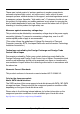
Hardware installation 4.2.1 Mounting the anti-tilt bracket I The anti-tilt bracket is only necessary for the redundant configuration (with two hot-plug power supplies). 0 0 Figure 2: Mounting the anti-tilt bracket Ê Place the server on the anti-tilt bracket. Ê Fasten the anti-tilt bracket using the two knurled screws (1).
Hardware installation 4.3 Installing/removing the rack model V CAUTION! ● Please observe the safety information and notes on rack mounting in chapter "Important information" on page 31. ● At least two people are needed to install / remove the server in the rack. (For the Japanese market, please refer to " 安全上の注意および その他の重要情報 ".) ● The rack may tip over if more than one unit is removed at the same time.
Hardware installation I For PRIMECENTER Racks and DataCenter Racks: The mounting of the rails in the different racks is described in the next sections. Installation of the cable management is described in detail in the Technical Manual for the respective rack. I For 19-inch standard rack (for the Japanese market): For information on mounting of the rails in the 19-inch standard rack (for the Japanese market) please refer to the next sections or the " はじめに お読みください ".
Hardware installation 100 mm 735 - 770 mm +/- 1,6mm Figure 3: Mechanical requirements TX200 S6 Operating Manual 51
Hardware installation – You must ensure that the safety mechanisms on the server, e.g. stoppers or retaining systems, are functioning correctly. – The shape of the rack support uprights must ensure that the support systems can be bolted to the front. The support systems have a linear alignment feature to ensure that they can be adjusted to different rack depths. – No cable management support (delivered with the mounting kit).
Hardware installation Fitting the support bracket When mounting the left support system in the corresponding rack, the supplied support bracket must first be mounted flush with the underside of the device on the rear left support upright. 0 2x / Figure 4: Fitting the support bracket Ê Position the support bracket at the corresponding height on the rear left support upright, (place the knobs in the corresponding holes) (1) and secure it with the two supplied M5 centering fixtures (2).
Hardware installation Installing the support systems 0 / 1 Figure 5: Fit the left support system in the PRIMECENTER/DataCenter rack Ê Position the left support system in the support bracket (insert retaining bolts) - see (1). I For the Japanese market: There is no support bracket. Please position the support system directly on the support upright.
Hardware installation I The support system no longer has to be fixed to the front support upright because the easy lock engages and ensures a firm fit. Ê Insert (3) the safety lock into the easy lock (snap fit). V CAUTION! Ensure that the safety lock has been inserted before the server is inserted! Ê Repeat the above steps for the right-hand support system (with the front and rear right support uprights).
Hardware installation Inserting the server 2 0 1 0 Figure 7: Inserting the server (a) 6 6 4 5 5 3 Figure 8: Inserting the server (b) 56 Operating Manual TX200 S6
Hardware installation V CAUTION! Ensure that the safety lock has been inserted before the server is inserted (see figure 5 on page 54). V CAUTION! At least two people are needed to position the server in the rack. (For the Japanese market, please refer to " 安全上の注意およびその他の 重要情報 ".) Ê Extend the telescopic rails completely to the front (1). I They must click into place so that they can no longer be moved. Ê Lower the server from above onto the projecting telescopic rails (2), (3).
Hardware installation I Under certain circumstances, you will not be able to use some of the parts from the rack installation kit supplied - you will need to use original 3rd party rack parts instead. Racks with installation depth of 735 mm The lengths of the telescopic rails do not need to be adjusted with respect to each other for the installation in rack systems with 735 mm installation depth. Ê Secure the support systems as described in section "Installing the support systems" on page 54.
Hardware installation 4.4 Connecting devices to the server The connectors for external devices are on the front and rear of the server. The additional connectors available on your server depend on the expansion cards installed.
Hardware installation Connecting the monitor Ê Connect the monitor to the video connector of the server (see figure 9 on page 59). Ê Connect the power cable of the monitor to a grounded mains outlet of the inhouse mains and/or to the mains socket strip of the rack. V CAUTION! The rated current for the monitor is indicated on the technical data label on the monitor or in the operating manual for the monitor. 4.
Hardware installation / 0 / 1 Figure 10: Connecting the server to the mains Ê Connect the power cord to the server power supply unit (1). Ê Connect the mains plug to a grounded mains outlet (2) in the in-house power supply network or a power outlet of the socket strip (3) in the rack (see technical manual for the rack).
Hardware installation 4.5.1 Using cable ties As an option, you can secure the power cable using a cable tie to ensure that the insulated connector cannot be disconnected from the server accidentally. The cable tie is included in the accessories pack that is delivered together with the server. 1 0 Figure 11: Using cable ties Ê Thread the cable tie through the eye (1). Ê Pull the cable tie tight to secure the power cable. The insulated connector cannot now be disconnected from the server accidentally.
Hardware installation 4.6 Notes on connecting/disconnecting cables V CAUTION! Always read the documentation supplied with the device you wish to connect. Never connect, or disconnect cables during a thunderstorm. Never pull on a cable when disconnecting it. Always take hold of the cable by the plug. Follow the sequence described below to connect or disconnect external devices to or from the server: Be sure to wait for 10 seconds or more after shutdown before turning the server on.
Hardware installation 64 Operating Manual TX200 S6
5 Starting up and operation V CAUTION! Follow the safety instructions in chapter "Important information" on page 31. 5.1 Access to the drives (floorstand model) 5.1.1 Access to the accessible drives 0 1 / Figure 12: Removing the drive cover and snapping it into the hard disk drive cover Ê Unlock the server (1). Ê Remove the drive cover (2). Ê Place the drive cover on the hard disk cover (3).
Starting up and operation Figure 13: Removing the drive cover from the hard disk drive cover Ê Carefully pull out on the green release lever (1) and lift off the drive cover (2).
Starting up and operation 5.1.2 Access to the HDD modules / 0 Figure 14: Removing the hard disk cover Ê Unlock the server (1). Ê Remove the hard disk cover (2). The hard disk drive cover is replaced and the server locked in the reverse order.
Starting up and operation 5.2 Control elements and indicators 5.2.
Starting up and operation 5.2.1.1 ID card You can pull out the ID card as far as it will go and push it back in again. The ID card contains various system information, such as the product name, serial number, order number, MAC addresses and DNS name. 5.2.1.2 Control elements On/Off button When the system is switched off, it can be switched on again by pressing the On/Off button. When the system is operating, pressing the On/Off button will switch off the system.
Starting up and operation 5.2.1.3 LEDs on the control panel Power indicator (two-color) Glows green when the server is switched on. Lights up orange when the server is switched OFF, but mains voltage is present (standby mode). Hard disk activity indicator (green) Lights up green when an internal hard disk drive is accessed. ! Global Error indicator (orange) – Lights up orange if a prefailure event has been detected that requires (precautionary) service intervention.
Starting up and operation CSS CSS indicator (yellow) – Lights up yellow if a prefailure event was detected for a CSS component that you can fix yourself (for reasons of precaution) with the CSS concept. – Flashes yellow if an error was detected that you can fix yourself with the CSS concept. – Does not light up when the system is OK. If the event is still acute after a power failure, the indicator is activated after the restart. The indicator also lights up in standby mode.
Starting up and operation Hard disk drive indicators 1 2 1 2 Figure 16: Indicators on the 3.5 inch and 2.
Starting up and operation 5.2.2 Rear of server 5.2.2.1 Indicators on the connector panel CSS, Global Error and ID indicators / Figure 17: Indicators on the connector panel: CSS, Global Error and ID indicators 1 CSS, Global Error and ID indicators (yellow, orange and blue) ! Global Error indicator (orange) – Lights up orange if a prefailure event has been detected that requires (precautionary) service intervention. – Flashes orange if an error was detected that requires service intervention.
Starting up and operation CSS CSS indicator (yellow) – Lights up yellow if a prefailure event was detected for a CSS component that you can fix yourself (for reasons of precaution) with the CSS concept. – Flashes yellow if an error was detected that you can fix yourself with the CSS concept. – Does not light up when the system is OK. If the event is still acute after a power failure, the indicator is activated after the restart. The indicator also lights up in standby mode.
Starting up and operation LAN indicators / 01 2 Figure 18: Indicators on the connector panel: LAN indicators 1 LAN activity indicator (management LAN) Lights up green if a LAN connection exists. Does not light up if no LAN connection exists. Flashes green when a LAN transfer is in progress. 2 LAN transfer rate indicator (management LAN) Lights up green for a LAN transfer rate of 100 Mbit/s. Does not light up for a LAN transfer rate of 10 Mbit/s.
Starting up and operation 5.2.2.2 Indicators on the hot-plug power supply unit / / Figure 19: Indicators on the hot-plug power supply units 1 Indicator on hot-plug power supply unit (two colors) Flashes green when the server is switched off, but mains voltage is present (standby mode). Lights up green when the server is switched on and functioning properly. Lights up orange if the power supply unit has failed.
Starting up and operation 5.3 Switching the server on and off V CAUTION! It nothing appears on the screen but flickering stripes after switching on the server, switch the server off immediately (see chapter "Troubleshooting and tips" on page 85). The On/Off button does not disconnect the server from the mains voltage. To completely disconnect it from the mains voltage, remove the power plug(s) from the socket(s).
Starting up and operation I If the operating system does not switch the server off automatically, press the On/Off button for at least four seconds and/or send a control signal for power button override. Other On/Off options Besides the On/Off button, the server can be switched ON and OFF in the following ways: – Timer-controlled switch-on/off Using the ServerView Operations Manager or iRMC S2, you can configure that the server is switched on/off controlled by timer.
Starting up and operation 5.4 Configuring the server This section contains information about configuring the server and installing the operating system. I Make sure that the power saving functions are disabled in the Power menu of the BIOS Setup during operation. 5.4.1 Configuring the onboard SATA controller A 6-port SATA controller is integrated on the system board. You can configure the onboard SATA controller either before or during installation with the ServerView Installation Manager.
Starting up and operation A separate utility is available to the controller for MegaRAID configuration. For further information, refer to the "SAS Software User’s Guide" (on the ServerView Suite DVD 2 under Industry Standard Servers Expansion Cards - Storage Adapters - LSI Configuration Software).
Starting up and operation If you are using the ServerView Installation Manager, you can skip the following section on how to configure the server and install the operating system. Continue from section "Cleaning the server" on page 82. 5.4.4 Configuring the server and installing the operating system without the ServerView Installation Manager Configure onboard SATA controller Configure the controller as described in section "Configuring the onboard SATA controller" on page 79.
Starting up and operation 5.5 Cleaning the server V CAUTION! Switch the server off and disconnect the power plugs from the properly grounded power outlets. Do not clean any interior parts yourself; leave this job to a service technician. Do not use any cleaning agents that contain abrasives or may corrode plastic. Ensure that no liquid enters the system. Ensure that the ventilation areas of the server and the monitor are clear. Do not use any cleaning sprays (including flammable types).
6 Property and data protection The floorstand model is protected against unauthorized opening by a lock. Apart from this, the server is also fitted with an intrusion detection switch which enables the ServerView Operations Manager program to detect and log any removal of the side cover or top cover and the cover for the HDD modules. To prevent it being removed from its location, the floorstand model can be secured to a fixed object with a steel cable running through a clip on the back.
Property and data protection 84 Operating Manual TX200 S6
7 Troubleshooting and tips V CAUTION! Follow the safety instructions in the "Safety notes and other important information" manual and in chapter "Important information" on page 31. If a fault occurs, attempt to resolve it using the measures described: – in this chapter, – in the documentation for the connected devices, – in the help systems of the software used. If you fail to correct the problem, proceed as follows: Ê Make a list of the steps performed and the circumstances that led to the fault.
Troubleshooting and tips 7.2 Server switches itself off Server Management has detected an error Ê Check the error list of System Event Log in ServerView Operations Manager or in the iRMC S2 web interface, and attempt to eliminate the error. 7.3 Screen remains blank Monitor is switched off Ê Switch on your monitor. Screen has gone blank Ê Press any key on the keyboard. or Ê Deactivate screen saver. Enter the appropriate password.
Troubleshooting and tips 7.4 Flickering stripes on monitor screen V CAUTION! Switch off the server immediately. Risk of damaging the server. Monitor does not support the set horizontal frequency Ê Find out which horizontal frequency your monitor screen supports. You will find the horizontal frequency (also known as line frequency or horizontal deflection frequency) in the documentation for your monitor.
Troubleshooting and tips 7.6 Incorrect date and time Ê Set the date and time in the operating system or in the BIOS Setup under the Main menu, using System Date and System Time respectively. I Note that the operating system may affect the system time. For example, the operating system time may deviate from the system time under Linux, and would overwrite the system time in the default setting on shutdown.
Troubleshooting and tips 7.8 Added drive reported as defective RAID controller is not configured for this drive The drive was probably installed when the system was switched off. Ê Reconfigure the RAID controller for the drive using the corresponding utility. Information is provided in the documentation for the RAID controller. or Ê Remove and reinstall the drive while the system is switched ON.
8 CSS components This chapter describes how to handle CSS components and how to identify defective CSS components and replace them yourself. I Further information on the CSS concept is provided in the "ServerView Suite Local Service Concept - LSC" manual on the ServerView Suite DVD 2. V CAUTION! Follow the safety instructions in the chapter "Important information" on page 31.
CSS components 8.1 Hot-plug components This section describes how to handle hot-plug components and how to modify your server hardware (e.g. adding/replacing hot-plug power supply units or hotplug HDD modules). The hot-plug procedure increases the availability of system operation and guarantees a high degree of data integrity and failsafe performance. 8.1.
CSS components Ê Remove the power cable from the installed power supply unit. Ê Push the green catch in the direction of the arrow (1) while pulling the power supply unit out of its mounting location (2) by the handle. Ê Slide the new power supply unit into the empty slot until the locking mechanism engages. I Make sure that the power supply unit engages correctly in the slot and is locked in position.
CSS components 94 ● Depending on the OS, you can configure the write cache settings for the hard disk drives. However, disable the write cache for use in this server. If the power failure should occur while the write cache is enabled, cached data may be lost. ● When disposing of, transferring, or returning a hard disk unit, wipe out the data on the drive for your own security. ● Rough handling of hard disk units can damage the stored data.
CSS components 8.1.2.1 / 3.5-inch HDD module and dummy module 0 0 1 2 3 4 5 Figure 21: 3.5-inch HDD module and dummy module 1 Dummy module 2 Tabs for unlocking the dummy module 3 HDD module (installation frame with hard disk drive installed) 4 Indicators HDD Busy (LED green) HDD Fault (LED orange) For description see section "Hard disk drive indicators" on page 72.
CSS components 8.1.2.2 2.5-inch HDD module and dummy module / 0 0 1 23 4 5 Figure 22: 2.5-inch HDD module and dummy module 1 Dummy module 2 Tabs for unlocking the dummy module 3 HDD module (installation frame with hard disk drive installed) 4 Indicators HDD Busy (LED green) HDD Fault (LED orange) For description see section "Hard disk drive indicators" on page 72.
CSS components 8.1.2.3 Handling hard disk drives and HDD modules Hard disk drives incorporated in the HDD modules are highly sensitive electromagnetic devices and must be handled with great care. Incorrect handling can cause partial or total failure of the hard disk drives. These failures can result in data errors and to a loss of data or to total corruption of the hard disk drive.
CSS components 8.1.2.4 Floorstand: removing the hard disk cover For a floorstand server you make the HDD modules accessible by removing the hard disk cover: / 0 Figure 23: Removing the hard disk cover Ê Unlock the server (1). Ê Remove the hard disk cover (2). The hard disk drive cover is replaced and the server locked in the reverse order.
CSS components 8.1.2.5 Removing/installing the dummy module Free slots are provided with dummy modules. Remove the dummy module before installing an additional HDD module. 1 1 2 Figure 24: Removing/installing the dummy module (example: 3.5-inch dummy module) Ê Press both tabs on the dummy module together until the locking mechanism disengages (1). Ê Pull the dummy module out of the slot (2). To install a dummy module, follow the same procedure in reverse order.
CSS components 8.1.2.6 Installing the HDD module Unlocking the HDD module 1 2 1 2 Figure 25: Unlocking the 3.5-inch and 2.5-inch HDD modules Ê Release the locking mechanism by pressing the locking button (1). Ê Push the handle of the HDD module fully in the direction of the arrow (2). The HDD module is now unlocked.
CSS components Installing the HDD module / 0 / 0 Figure 26: Installing the 3.5-inch and 2.5-inch HDD modules Ê Unlock the HDD module as described in section "Unlocking the HDD module" on page 100. Ê Carefully push the HDD module into the empty slot (1) until it stops. Ê Push the handle of the HDD module as far as it will go in the direction of the arrow (2) until the locking mechanism is engaged.
CSS components 8.1.2.7 Removing the HDD module V CAUTION! ● Only remove a HDD module during operation if the drive is not currently being accessed. Observe the control LEDs for the corresponding HDD modules (see "Hard disk drive indicators" on page 72). ● Under no circumstances should you remove a HDD module while the system is in operation if you are not sure that the hard disk drive is operated by a RAID controller and belongs to a disk array that is operating in RAID level 1, 5 or 6.
CSS components Ê Install the new HDD module, as described in "Installing the HDD module" on page 101. V CAUTION! If you have removed a HDD module and do not install a new one in its place, put the dummy module back in its place for cooling, to comply with EMC regulations (regulations regarding electromagnetic compatibility), and for protection against fire. Ensure that the dummy module engages correctly in the bay. 8.
CSS components 8.2.1 Opening the server and identifying the defective CSS component 8.2.1.1 Opening the server V CAUTION! The device can be seriously damaged if it is opened without authorization or if repairs are attempted by untrained personnel. It is essential to observe the safety instructions in chapter "Important information" on page 31. 1 0 / Figure 27: Opening the server (example: floorstand model) Ê Unlock the server. Ê Pull the locking lever as far as it will go (1).
CSS components 8.2.1.2 Removing system fan 2 (and 4) Figure 28: System fan 2 and system fan 2&4 The standard system fan 2 has just one fan cable; the redundant system fan 2&4 (double fan) has two fan cables (as two fans are integrated internally). The procedure for installing and removing both system fans is identical except for connecting the fan cables.
CSS components Ê Disconnect the fan cable from the connector FAN2 (if there is a second fan cable, disconnect this from FAN4) on the system board (see the technical manual for the system board D2799). Ê Press the two green locks of the air duct together (1). Ê Press the green lock of the air duct in the direction of the arrow (2). Ê Lift the air duct with the integrated system fan 2 (and 4) up and out (3). 8.2.1.
CSS components Figure 31: Example: Removing system fan 1&3 Ê Disconnect the fan cable from the connector FAN1 on the system board (if there is a second fan cable, disconnect this from FAN3). Ê Push the locking lever in the direction of the arrow (1). Ê Pull system fan 1 (and 3) in the direction of the arrow (2) to disengage the four hooks. Ê Take system fan 1 (and 3) out (3). 8.2.1.
CSS components 8.2.2 Replacing a memory module 8.2.2.1 Removing a defective memory module 2 1 1 Figure 32: Removing a memory module Ê Press the securing clips on both sides of the memory slot concerned outward. (1). Ê Pull the defective memory module out of the slot (2). 8.2.2.2 Installing a new memory module V CAUTION! Please note the equipping rules in the technical manual for the system board D2799.
CSS components 8.2.3 Replacing the system fan V CAUTION! Since the standard system fans 1 and 2 are not redundant, these system fans have to be replaced immediately. If one of the four redundant system fans (1&3 and 2&4) fails, one of the two predetermined fans (system fan 3 and 4) increases its power to ensure that the server is cooled properly. The redundant system fans should be replaced as soon as possible. 8.2.3.
CSS components 8.2.4 Replacing an expansion card 8.2.4.1 Removing a defective expansion card Figure 34: Removing a defective expansion card Ê If necessary, remove the cables from the defective expansion card. Ê Push the lever upwards (1). Ê Press onto the clip and remove it. Ê Pull the defective expansion card out of its slot (2).
CSS components 8.2.4.2 Installing a new expansion card Figure 35: Installing a new expansion card Ê Carefully press the new expansion card into the slot until it clicks into place (1). Make sure that the lug on the slot cover clicks into place in the corresponding hole. Ê Fit the clip onto the slot cover so that the pin fits into the hole. Ê Push the clip under the metal nose until it clicks into place. Ê Swing the lever (2) downwards into its locking position.
CSS components 8.2.5 Reinstalling the fans and closing the server 8.2.5.1 Installing system fan 1 (and 3) Figure 36: Installing system fan 1 (and 3) Ê Place the hooks of system fan 1 (and 3) into the recesses on the rear of the server (1). Ê Push system fan 1 (and 3) in the direction of the arrow until the locking lever engages (2).
CSS components 8.2.5.2 Installing system fan 2 (and 4) Ê Connect the fan cable to the connector FAN2 (if there is a second fan cable, connect this in FAN4) on the system board (see the technical manual for the system board D2799). Figure 37: Installing system fan 2 (and 4) Ê Carefully insert the air duct with the integrated system fan 2 (and 4) (1).
CSS components 8.2.5.3 Closing the server / 0 0 Figure 38: Closing the server (example: floorstand model) Ê Pull the locking lever as far as it will go and insert the side cover in the five recesses (see small arrows) of the housing (1). Ê Press the side cover against the housing and at the same time push the locking lever shut (2). Closing the locking lever pushes the side cover forwards and the hooks on the upper edge of the side cover engage.
9 Appendix: server specification This section explains the specifications for the server. The specifications for this server are liable to be updated without any notice. Please be forewarned. System Board System board type D2799 Chipset Intel 5500 Processor Processor quantity and 1or 2 Intel Xeon processors type Memory Modules Configuration Memory slots 12 Memory slot type DIMM (DDR3) Memory capacity (min. - max.
Appendix: server specification Serial 2 (9-pin) 1 x serial RS-232-C, optional - occupies an unused slot LAN / Ethernet (RJ-45) 1 x Gbit/s Ethernet Service LAN (RJ45) 1 x dedicated service LAN connector for iRMC S2 (10/100 Mbit/s) Service LAN traffic can be switched to shared onboard Gbit LAN port Onboard or integrated controllers RAID Controller Modular RAID 0/1 controller with "Integrated Mirroring Enhanced" (SAS IME) for SAS1.0.
Appendix: server specification PCI-Slots PCI-Express 2.0 x4 (mech. x8) 2 x full height (1x long, 1x short) PCI-Express 2.0 x8 2 x full height (1x notched, thus usable for x16 cards operating in x8 mode) PCI-Express x4 (mech.
Appendix: server specification Service displays (optional): ServerView Local Service Panel (LSP) ServerView Local Service Display (LSD) Weight Weight up to 36.
Appendix: server specification Electrical values Power supply configuration 1x standard, 1x hot-plug or 2x redundant Max. output of single power supply 685 W Standard power supply 700 W output Hot-plug power supply output 800 W Rated voltage range 100 - 240 V Rated frequency range 47- 63 Hz Rated current TX200 S6 max. 9.5 A – 4.
Appendix: server specification 120 Operating Manual TX200 S6
Index USB connector 59 video connector 59 consumables 43 control elements 68 control panel 68 correcting faults 85 CSS indicator 68, 71, 74 3rd party rack installing in 57 requirements 50 A acclimatization time 45, 97 Advanced Video Redirection ambient conditions 27 ASR&R 20 availability 20 AVR 21 21 B batteries 35 BIOS security functions 83 BIOS update 23 C cables connecting 63 disconnecting 63 CE marking 26, 40 Class A Compliance Statement 40 cleaning keyboard 82 monitor 82 mouse 82 server 82 closing,
Index environmental protection 43 error drifting display on monitor 87 drive “dead” 88 drive defective 89 incorrect date 88 incorrect time 88 no display on monitor 87 power-on indicator does not light 85 screen remains blank 86 screen shows flickering stripes 87 server switches itself off 86 Error Correcting Code 20 Error Detection Code 20 error message on screen 89 expansion card installing 111 replacing 110 expansion card, removing 110 F fault drifting display on monitor 87 drive defective 89 incorrect da
Index L labels 44 LAN activity indicator 75 LAN transfer rate, indicator 75 laser information 37 light emitting diode (LED) 37 lithium battery 35 Low Voltage Directive 26, 40 M MAC address 69 Main memory 108 mains voltage, connecting server 60 management LAN connector 21, 59 meaning of the symbols 25 MegaRAID 17, 79 memory module hot-spare memory 20 inserting 108 removing 108 memory scrubbing 20 monitor display drifts 87 no display 87 Mounting the anti-tilt bracket 48 power supply unit cable clamp 62 hot-p
Index SAS/SATA RAID controller 17 configuring 79 saving energy 43 screen error message 89 flickering 87 remains blank 86 shows flickering stripes 87 SDDC, Single Device Data Correction 20 security function 11 serial number 46, 69 server closing 114 configuration 23, 79 connecting external devices 59 connecting mains voltage 60 connectors 59 control panel 68 correcting faults 85 data protection 83 dimensions 27 electrical data 26 fitting in rack 49 hot-plug power supply unit 92 indicators 68 installing 49 LA
Index service 23 TPM 15 transport damage 29, 46 transporting the server 41 troubleshooting 85 Trusted Platform Module 15 U unpacking, server 46 USB connector 59, 68 using the cable clamp 62 V ventilation clearance 27 video connector 59 W weight TX200 S6 27 Operating Manual 125