PRIMERGY TX300 S5 Operating manual Edition September 2009
Comments… Suggestions… Corrections… The User Documentation Department would like to know your opinion of this manual. Your feedback helps us optimize our documentation to suit your individual needs. Feel free to send us your comments by e-mail to manuals@ts.fujitsu.com.
Contents 1 Preface . . . . . . . . . . . . . . . . . . . . . . . . . . . . . . 7 1.1 Concept and target groups for this manual 1.2 Documentation overview 1.3 Features . . . . . . . . . . . . . . . . . . . . . . . . . . . . . . 9 1.4 Notational conventions 1.5 Technical data 2 Installation steps, overview . . . . . . . . . . . . . . . . . . 23 3 Important information . . . . . . . . . . . . . . . . . . . . . 25 3.1 Safety instructions . . . . . . . . . . . . . . . . . . . . . . . 25 3.
Contents 4.5 4.5.1 Connecting the server to the mains . . . . . . . . . . . . . . 61 Using cable ties . . . . . . . . . . . . . . . . . . . . . . . . . . 63 4.6 Notes on connecting/disconnecting cables . . . . . . . . . . 64 5 Starting up and operation . . . . . . . . . . . . . . . . . . . . 65 5.1 5.1.1 5.1.2 Access to the drives . . . . . . . . . . . . . . . . . . . . . . . 65 Access to the accessible drives (floorstand model) . . . . . . . . 65 Access to the HDD modules (floorstand model) . . . .
Contents 7.4 Flickering stripes on monitor screen . . . . . . . . . . . . . 87 7.5 No screen display or display drifts . . . . . . . . . . . . . . 87 7.6 Incorrect date and time 7.7 Hard disk drive error messages at system boot . . . . . . . 88 7.8 Added drive reported as defective . . . . . . . . . . . . . . 89 7.9 Error message on screen . . . . . . . . . . . . . . . . . . . 89 8 CSS components . . . . . . . . . . . . . . . . . . . . . . . . 91 8.1 8.1.1 8.1.1.1 8.1.2 8.1.2.1 8.1.2.2 8.1.2.
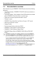
1 Preface With top dual processor performance, the PRIMERGY TX300 S5 tower server is an all-purpose server for medium sized companies and branches of large enterprises. The system is ideal for use as a versatile business server for business critical applications and dedicated tasks. Thanks to internal SAS/SATA hard disk capacity of up to 6 or 8 TB, the PRIMERGY TX300 S5 is also suitable for use as a platform for highly data intensive solutions.
Preface Documentation overview 1.
Preface Features Further sources of information: – PRIMERGY Abbreviations and Glossary on the PRIMERGY ServerView Suite DVD 2 – Manual for the monitor – Documentation for the boards and drives – Operating system documentation – Information files in your operating system 1.3 Features Customer Self Service (CSS) The Fujitsu Technology Solutions Customer Self Service (CSS) concept enables you to identify and replace the affected component yourself in the case of certain error scenarios.
Preface Features In the event of errors, the ServerView Operations Manager refers you directly to the affected component and its order information in the Illustrated Spares catalog of the server in question. System board The features of the system board are described in the technical manual for the system board D2619 for the hardware and in the BIOS Setup manual for the firmware. Trusted Platform Module (TPM) A Trusted Platform Module (TPM) for safer storage of keys can be implemented as an option.
Preface Features Fujitsu Technology Solutions offers a unique patented solution to deliver the highest possible bandwidth with four PCIe Gen2 x8 slots: two of the four PCIe Gen2 x4 slots can each be used as PCIe Gen2 x8 slots if the neighboring slot is free. Hard disk drives The server is shipped with one of the following drive cages: – For up to six 3.5-inch SAS/SATA hard disk drives: Up to six SAS/SATA HDD modules can be used in the drive cage.
Preface Features SAS/SATA RAID controller The server is available with the following SAS/SATA RAID controllers for operating the internal SAS/SATA hard disk drives: – Modular RAID 0/1 controller with "Integrated Mirroring Enhanced" (SAS IME) RAID levels 0, 1 and 1E are supported for internal hard disk drive configurations. For more information on configuring the controller, see section "Configuring the server" on page 79.
Preface Features – In the two lower bays, you can install the Multibay 2. The Multibay 2 has bays for two additional 3.5-inch hard disk drives, a Slimline DVD drive and the ServerView Local Service Panel (LSP) or the ServerView Local Service Display (LSD). – You can install the Multibay 1 in the bottom bay (see above) and the expansion box for 2.5-inch SAS hard disk drives in the two upper bays (see also section "Hard disk drives" on page 11).
Preface Features High level of availability and data security When memory data is accessed, 1-bit errors are identified in the main memory and automatically corrected with the error correcting code (ECC) method. The patented memory scrubbing function regularly starts up the EDC mechanism, ensuring continuous data integrity. The memory modules used support SDDC technology (Chipkill™), which further increases the effectiveness of memory error monitoring and correction.
Preface Features iRMC S2 with integrated service LAN port I The features of the iRMC S2 Advanced Video Redirection and Remote Storage are available as an option. The iRMC S2 (integrated Remote Management Controller) is a BMC with integrated service LAN port and expanded functionality that was previously only available with additional plug-in cards.
Preface Features Server management Server management is implemented using the ServerView Operations Manager supplied combined with PDA (Prefailure Detection and Analysis) technology from Fujitsu Technology Solutions. PDA reports the threat of a system error or overload at an early stage, allowing preventive measures to be taken. The ServerView Operations Manager enables the management of all PRIMERGY servers in the network via a central console.
Preface Features ServerView Installation Manager You can configure the PRIMERGY server quickly and precisely with the ServerView Installation Manager software provided. User-guided menus are available for installing the server operating system (for further details see section "Configuring the server" on page 79). Service and support PRIMERGY servers are service-friendly and modular, enabling quick and easy maintenance.
Preface Features ServerView Remote Management ServerView Remote Management is the remote management solution from Fujitsu Technology Solutions for PRIMERGY servers. ServerView Remote Management and the relevant hardware components integrated on the system board allow remote monitoring and maintenance as well as fast restoration of operation in the event of errors. Remote monitoring and maintenance avoids time-consuming and costly on-site repairs and reduces service costs.
Preface 1.4 Notational conventions Notational conventions The following notational conventions are used in this manual: Text in italics indicates commands or menu items. "Quotation marks" indicate names of chapters and terms that are being emphasized. Ê describes activities that must be performed in the order shown. V CAUTION! pay particular attention to texts marked with this symbol. Failure to observe this warning may endanger your life, destroy the system or lead to the loss of data.
Preface Technical data Compliance with regulations and standards Product safety and ergonomics International IEC 60950-1 Europe Safety EN 60950-1 Ergonomics ISO 9241-3 EN 2941-3 EK1-ITB 2003:2007 UL 60950-1 USA / Canada CSA-C22.
Preface Technical data Mechanical values Floorstand model Rack model Width 286 mm (with feet) 483 mm (front panel) Total depth 745 mm 748 mm (with handles) Installation depth ------- 710 mm (without handles) Height 466 mm (with feet) 177 mm or 4 HU Weight Approx. 25 - 40 kg (depending on configuration). Ventilation clearance At least 200 mm on the front and rear. Maintenance area for the floorstand model 1.2 m2 on the left side. Emergency access must be assured.
Preface Technical data Noise level with standard fan modules and one hot-plug power supply unit Sound power level LWAd (ISO 9296) ≤ 5.2 B (standby) ≤ 5.
2 Installation steps, overview This chapter contains an overview of the steps you need to carry out to install your server. Links take you to sections where you can find more detailed information about the respective steps: Ê First of all, it is essential that you familiarize yourself with the safety information in chapter "Important information" on page 25.
Installation steps, overview Ê Configure the server and install the desired operating system and applications. The following options are available: – Remote installation with the ServerView Installation Manager: With the PRIMERGY ServerView Suite DVD 1 provided, you can configure the server and install the operating system in a convenient manner.
3 Important information In this chapter you will find essential information regarding safety when working on your server. 3.1 Safety instructions I The following safety instructions are also provided in the manual "Safety notes and other important information". This device meets the relevant safety regulations for IT equipment. If you have any questions about whether you can install the server in the intended environment, please contact your sales outlet or our customer service team.
Important information Safety instructions Before starting up V CAUTION! ● During installation and before operating the device, observe the instructions on environmental conditions for your device. ● If the device is brought in from a cold environment, condensation may form both inside and on the outside of the device. Wait until the device has acclimatized to room temperature and is absolutely dry before starting it up. Material damage may be caused to the device if this requirement is not observed.
Important information Safety instructions V CAUTION! ● Ensure that the power sockets on the device and the grounded shockproof sockets are freely accessible. ● The On/Off button or the main power switch (if present) does not isolate the device from the mains power supply. To disconnect it completely from the mains power supply, unplug all network power plugs from the grounded shockproof sockets. ● Always connect the server and the attached peripherals to the same power circuit.
Important information Safety instructions V CAUTION! 28 ● Proper operation of the system (in accordance with IEC 60950-1/ EN 60950-1) is only ensured if the casing is completely assembled and the rear covers for the installation slots have been fitted (electric shock, cooling, fire protection, interference suppression). ● Only install system expansions that satisfy the requirements and rules governing safety and electromagnetic compatibility and those relating to telecommunication terminals.
Important information Safety instructions Batteries V CAUTION! ● Incorrect replacement of batteries may lead to a risk of explosion. The batteries may only be replaced with identical batteries or with a type recommended by the manufacturer (see the technical manual for the system board). ● Do not throw batteries into the trash can. They must be disposed of in accordance with local regulations concerning special waste.
Important information Safety instructions Working with CDs/DVDs and CD/DVD drives When working with devices with CD/DVD drives, these instructions must be followed. V CAUTION! ● Only use CDs/DVDs that are in perfect condition in your server's CD/DVD drive, in order to prevent data loss, equipment damage and injury. ● Check each CD/DVD for damage, cracks, breakages etc. before inserting it in the drive.
Important information Safety instructions Modules with Electrostatic-Sensitive Devices Modules with electrostatic-sensitive devices are identified by the following sticker: Figure 1: ESD label When you handle components fitted with ESDs, you must always observe the following points: ● Switch off the system and remove the power plugs from the power outlets before installing or removing components with ESDs. ● You must always discharge static build-up (e.g.
Important information ENERGY STAR Other important information: ● During cleaning, observe the instructions in section "Cleaning the server" on page 82. ● Keep this operating manual and the other documentation (such as the technical manual, CD) close to the device. All documentation must be included if the equipment is passed on to a third party. 3.2 ENERGY STAR Products that have been certified compliant with ENERGY STAR and identified as such are in full compliance with the specification at shipping.
Important information 3.4 FCC Class A Compliance Statement FCC Class A Compliance Statement If there is an FCC statement on the device, then: The following statement applies to the products covered in this manual, unless otherwise specified herein. The statement for other products will appear in the accompanying documentation.
Important information Transporting the server WARNING: This is a class A product. In a domestic environment this product may cause radio interference in which case the user may be required to take adequate measures. 3.5 Transporting the server V CAUTION! Only transport the server in its original packaging or in packaging that protects it from impacts and jolts. Do not unpack the server until it is at its installation location. If you need to lift or transport the server, ask other people to help you.
Important information 3.6 Notes on installing in the rack Notes on installing in the rack V CAUTION! ● For safety reasons, at least two people are required to install the rack model because of its weight and size. ● Never lift the server into the rack using the handles on the front panel. ● When connecting and disconnecting cables, observe the relevant instructions in the "Important Information" chapter of the technical manual for the corresponding rack.
Important information Environmental protection 3.7 Environmental protection Environmentally-friendly product design and development This product has been designed in accordance with the Fujitsu Technology Solutions standard for "environmentally friendly product design and development". This means that key factors such as durability, selection and labeling of materials, emissions, packaging, ease of dismantling and recycling have been taken into account.
Important information Environmental protection Labels on plastic casing parts Please avoid sticking your own labels on plastic parts wherever possible, since this makes it difficult to recycle them. Returns, recycling and disposal The device must not be disposed of with domestic waste. This device is labeled in compliance with European directive 2002/96/EC on waste electrical and electronic equipment (WEEE).
4 Hardware installation V CAUTION! ● Follow the safety instructions in the chapter "Important information" on page 25. ● Do not expose the server to extreme environmental conditions (see "Ambient conditions" on page 21). Protect the server from dust, humidity and heat. ● Make sure that the server is acclimatized for the time indicated in this table before putting it into operation.
Hardware installation Unpacking the server 4.1 Unpacking the server V CAUTION! Follow the safety instructions in chapter "Important information" on page 25. The server must always be lifted or carried by at least two people. Do not unpack the server until it is at its installation location. Ê Transport the server to the place where you want to set it up. Ê Unpack all individual parts. Keep the original packaging in case you want to transport the server again.
Hardware installation Setting up the floorstand model – Ensure that there is enough unobstructed area around the server for operating and servicing the device (see "Maintenance area for the floorstand model" on page 21). – Access to the rear of the server must be assured so that other devices (e.g. memory subsystems) can be connected. – The mains plug must be accessible easily and safely. – A clearance of at least 200 mm must be maintained in front of and behind the system to ensure proper ventilation.
Installing/removing the rack model 4.3 Hardware installation Installing/removing the rack model V CAUTION! 4.3.1 ● Please observe the safety information and notes on rack mounting in chapter "Important information" on page 25. ● Several people are needed to install / remove the server in the rack. ● The rack can tip over if more than one unit is pulled out.
Hardware installation Installing/removing the rack model PRIMECENTER/DataCenter Rack The main features of the rack systems from Fujitsu Technology Solutions are as follows: – Support systems that can be mounted without tools The support systems have a linear alignment feature to ensure that they can be adjusted to different rack depths. – Enhanced cable management in the lateral rack area The mounting of the rails in the different racks is described in the next sections.
Installing/removing the rack model Hardware installation 3rd party racks Certain general conditions must be met: – Installation dimensions (see the dimensions shown in figure 2 on page 45).
Hardware installation Installing/removing the rack model Figure 2: Mechanical requirements TX300 S5 Operating manual 45
Installing/removing the rack model Hardware installation – Ensure that the safety mechanisms on the server, e.g. stoppers or retaining systems, are functioning correctly. – The shape of the rack support uprights must ensure that the telescopic rails can be bolted at the front. – Telescopic rails screwed to the front The rails have a linear alignment feature to ensure that they can be adjusted to different rack depths (710 - 785 mm). – No cable management support (delivered with the mounting kit).
Hardware installation 4.3.2 Installing/removing the rack model Installation in PRIMECENTER/DataCenter rack For installation in a PRIMECENTER/DataCenter rack, the following parts are required: – Support bracket – One support system on the left and one on the right – M5 centering fixtures (screws with integrated plugwashers) I General information regarding server installation in the rack is included in the technical manual for the appropriate rack.
Installing/removing the rack model Hardware installation Mounting the support system 2 1 3 Figure 4: Mounting the left support system Ê Place the left support system in the support bracket with the two retaining bolts in the two outer square catches (1). Ê Clamp the left support system between the front left support upright and the support bracket by pressing it together, positioning it on the front support upright and releasing it again (2).
Hardware installation Installing/removing the rack model Inserting the server V CAUTION! At least two people are needed to position the server in the rack. 5 2 7 7 6 1 3 6 4 Figure 5: Inserting the server Ê Pull the mounted support systems forwards as far as they will go until they engage. The telescopic rails must not be able to move backwards any more. Ê Lift the server onto the left and right system support rods (1).
Installing/removing the rack model Hardware installation The following steps can be carried out by one person only. Ê Press the safety springs (5) on both telescopic rails and slide the server as far as it will go into the rack (6). Ê Fasten the server using two knurled screws (7). Ê Route the cables as described in the technical manual for the rack in question with the server pushed in. To remove the server, follow this procedure in reverse. 4.3.
Hardware installation Installing/removing the rack model Figure 6: Mounting the telescopic rail in the Classic Rack Ê Secure the right and left adapters to the support uprights in the rack with two (M5) screws each. Note that the guide nubs on the support systems must fit into the holes in the support uprights next to the spring nuts. Ê Secure the left and right support systems to the adapters in the rack with two (M5) screws and nuts each.
Installing/removing the rack model Hardware installation Fitting the articulated cable guide (cable management) V CAUTION! In contrast to the instructions in the Technical Manual for the 19" (Classic) Rack the articulated cable guide is only secured to the support upright not to the server. Ê To secure the articulated cable guide, place two spring nuts in the groove in the rear right support upright. The installation height shall correspond to the height of the connecting cables on the server.
Hardware installation Installing/removing the rack model Figure 8: Routing the cables on the articulated cable guide Ê Route the cables as shown in the figure and secure them to the articulated cable carrier with cable ties (1). V CAUTION! To prevent the Fibre Channel fiber optic cables from being damaged, they are sheathed in a protective tube (see the next section "Routing the fiber channel fiber optic cable").
Installing/removing the rack model Hardware installation Routing the fiber channel fiber optic cable The protective hose (length approx. 1 m) supplied with the mounting kit has a separable design. Figure 9: Fitting the protective hose Ê Separate the outer protective sheath (1) from the inner sheath. Ê Carefully place the fiber optic cable (3) in the inner protective sheath (2). Ê Push the outer protective sheath (1) over the inner protective sheath.
Hardware installation Installing/removing the rack model Figure 10: Routing the fiber optic cable with protective hose Ê Route the fibre channel optical waveguide cable on the articulated cable carrier as shown in the figure and secure them with cable ties (1). V CAUTION! Make sure that the radii are designed in such a way that no damage can occur to the protected fiber optic cable with the articulated cable guide extended or retracted.
Installing/removing the rack model Hardware installation Figure 11: Extending the telescopic rail Ê Pull the telescopic rails forward as far as they will go until they engage. The telescopic rails must not be able to move backwards any more.
Hardware installation Installing/removing the rack model 1 2 Figure 12: Installing the server (Classic Rack) Ê Lift the server onto the left and right system support rods (1). V CAUTION! Hold the server on both sides when lifting it onto the left and right system support rods, not just by the handles on the front panel! Ê Position the server so that the holes of the left and right system support rods are in line with those of the server.
Installing/removing the rack model Hardware installation Figure 13: Telescope rail with safety spring Ê Press in the safety springs (1) on both telescope rails. Figure 14: Fastening the server in the rack cabinet Ê Slide the server into the rack. Ê Fasten the server using two knurled screws. Ê Route the cables once the server has been inserted, as described in the Technical Manual for the classic rack. To remove the server, follow this procedure in reverse.
Hardware installation 4.3.4 Installing/removing the rack model Installation in 3rd party racks The procedure for installing in 3rd party racks is basically as described in "Installation in PRIMECENTER/DataCenter rack" on page 47 (the support bracket and cable management are not installed).
Hardware installation Connecting devices to the server 4.4 Connecting devices to the server The ports for external devices are on the rear of the server. The additional ports available on your server depend on the expansion cards installed. The standard ports (figure 15) are marked with symbols, and some are color-coded.
Hardware installation Connecting the server to the mains The corresponding indicators are explained in section "Rear of server" on page 73. I Some of the devices connected require special software (e.g. drivers) (see documentation for the connected device). Ê Connect the devices. Three additional USB ports are located on the front of the server (see figure 21 on page 68). I If components with large power requirements (e.g.
Hardware installation Connecting the server to the mains 2 1 1 2 Figure 16: Connecting the server to the mains (example: rack model) Ê Connect the insulated connector of the power cable to power supply unit of the server (1), and the power plug to a grounded mains outlet (2) of the inhouse mains and/or into the mains socket strip of the rack (see Technical Manual of the rack). I A phase redundancy in the power supply of the server can be set up if two hot-plug power supply units are installed.
Hardware installation 4.5.1 Connecting the server to the mains Using cable ties As an option, you can secure the power cable using a cable tie to ensure that the insulated connector cannot be disconnected from the power supply unit accidentally. The cable tie is included in the accessories pack that is delivered together with the server. 1 2 Figure 17: Using cable ties Ê Thread the cable tie through the eye (1). Ê Pull the cable tie tight to secure the power cable.
Notes on connecting/disconnecting cables 4.6 Hardware installation Notes on connecting/disconnecting cables V CAUTION! Always read the documentation supplied with the device you wish to connect. Never connect, or disconnect cables during a thunderstorm. Never pull on a cable when disconnecting it. Always take hold of the cable by the plug. Follow the sequence described below to connect or disconnect external devices to or from the server: Connecting cables Ê Turn off all power and equipment switches.
5 Starting up and operation V CAUTION! Follow the safety instructions in chapter "Important information" on page 25. 5.1 Access to the drives 5.1.1 Access to the accessible drives (floorstand model) 2 3 1 Figure 18: Removing the drive cover and placing it on the hard disk cover Ê Unlock the server (1). Ê Remove the drive cover (2). Ê Place the drive cover on the hard disk cover (3).
Starting up and operation Access to the drives I Please note the following when operating with tape drives: If the system is programmed to eject the media automatically, the accessible drives must not be obstructed. Figure 19: Removing the drive cover from the hard disk drive cover Ê Lift the drive cover in the direction of the arrow to remove it from the hard disk cover. The drive cover is replaced and the server locked in the reverse order.
Starting up and operation 5.1.2 Access to the drives Access to the HDD modules (floorstand model) 1 2 Figure 20: Removing the hard disk cover Ê Unlock the server (1). Ê Remove the hard disk cover (2). The hard disk drive cover is replaced and the server locked in the reverse order.
Starting up and operation Controls and indicators 5.2 Controls and indicators 5.2.
Starting up and operation 5.2.1.1 Controls and indicators ID card You can pull out the ID card as far as it will go and push it back in again. The ID card contains various system information, such as the product name, serial number and MAC addresses. 5.2.1.2 Controls On/Off button When the system is switched off, it can be switched on again by pressing the On/Off button. When the system is operating, pressing the On/Off button will switch off the system.
Starting up and operation Controls and indicators 5.2.1.3 Indicators on the control panel Power-on indicator (two colors) Lights up green when the server is switched ON. Lights up orange when the server is switched OFF, but mains voltage is present (standby mode). Hard disk activity indicator (green) Lights up green when an internal drive (HDD or backup drive) is being accessed.
Starting up and operation CSS Controls and indicators CSS indicator (yellow) – Lights up yellow if a prefailure event was detected for a CSS component that you can fix yourself (for reasons of precaution) with the CSS concept. – Flashes yellow if an error was detected that you can fix yourself with the CSS concept. – Does not light up when the system is OK. If the event is still acute after a power failure, the indicator is activated after the restart. The indicator also lights up in standby mode.
Starting up and operation Controls and indicators Hard disk drive indicators 1 2 1 2 Figure 22: Indicators on the 3.5 inch and 2.
Starting up and operation Controls and indicators 5.2.2 Rear of server 5.2.2.
Starting up and operation Controls and indicators ! Global Error indicator (orange) – Lights up orange if a prefailure event has been detected that requires (precautionary) service intervention. – Flashes orange if an error was detected that requires service intervention. – Does not light up if there is no critical event. If the event is still acute after a power failure, the indicator is activated after the restart. The indicator also lights up in standby mode.
Starting up and operation Controls and indicators LAN indicators 1 2 3 4 3 4 Figure 24: Indicators on the connection panel: LAN indicators 1 LAN activity indicator (service LAN) Lights up green if a LAN connection exists. Does not light up if no LAN connection exists. Flashes green when a LAN transfer is in progress. 2 LAN transfer rate indicator (service LAN) Lights up green for a LAN transfer rate of 100 Mbit/s. Does not light up for a LAN transfer rate of 10 Mbit/s.
Starting up and operation Controls and indicators 5.2.2.2 Indicator on hot-plug power supply unit 1 1 Figure 25: Indicator on hot-plug power supply unit 1 Indicator on hot-plug power supply unit (two colors) Flashes green when the server is switched off, but mains voltage is present (standby mode). Lights up green when the server is switched on and functioning properly. Lights up orange if the power supply unit has failed.
Starting up and operation 5.3 Switching the server on and off Switching the server on and off V CAUTION! It nothing appears on the screen but flickering stripes after switching on the server, switch the server off immediately (see chapter "Troubleshooting and tips" on page 85). The On/Off button does not disconnect the server from the mains voltage. To completely disconnect it from the mains voltage, remove the power plug(s) from the socket(s).
Switching the server on and off Starting up and operation I If the operating system does not switch the server off automatically, press the On/Off button for at least four seconds and/or send a corresponding control signal for power button override.
Starting up and operation 5.4 Configuring the server Configuring the server This section contains information about configuring the server and installing the operating system. 5.4.1 Configuring the SAS/SATA RAID controller The server has a SAS/SATA RAID controller with "Integrated Mirroring Enhanced" functionality or "MegaRAID functionality". You can configure the SAS/SATA RAID controller either before or during installation with the ServerView Installation Manager.
Starting up and operation Configuring the server 5.4.2 Configuring the server and installing the operating system with the ServerView Installation Manager Using the ServerView Installation Manager on the PRIMERGY ServerView Suite DVD 1 provided, you can conveniently configure the server and install the operating system. This includes configuring the server-specific settings using the ServerView Configuration Manager and configuring the RAID controller using the ServerView RAID Manager.
Starting up and operation 5.4.3 Configuring the server Configuring the server and installing the operating system without the ServerView Installation Manager Configuring SAS/SATA RAID controller with "Integrated Mirroring Enhanced" Configure the controller as described in section "Configuring the SAS/SATA RAID controller" on page 79. Configuring SAS/SATA RAID controller with "MegaRAID functionality" Configure the controller as described in section "Configuring the SAS/SATA RAID controller" on page 79.
Starting up and operation Cleaning the server 5.5 Cleaning the server V CAUTION! Switch the server off and disconnect the power plugs from the grounded shockproof sockets. Do not clean any interior parts yourself; leave this job to a service technician. Do not use any cleaning agents that contain abrasives or may corrode plastic. Ensure that no liquid enters the system. Ensure that the ventilation areas of the server and the monitor are clear. Clean the keyboard and the mouse with a disinfecting cloth.
6 Property and data protection The floorstand model is protected against unauthorized opening by a lock. Apart from this, the server is also fitted with an intrusion detection switch which enables the ServerView Operations Manager to detect and log any removal of the left cover or housing cover and the cover for the HDD modules. To prevent it being removed from its location, the floorstand model can be secured to a fixed object with a steel cable running through a clip on the back.
7 Troubleshooting and tips V CAUTION! Follow the safety instructions in the "Safety notes and other important information" manual and in chapter "Important information" on page 25. If a fault occurs, attempt to resolve it using the measures described: – in this chapter, – in the documentation for the connected devices, – in the help systems of the software used. If you fail to correct the problem, proceed as follows: Ê Make a list of the steps performed and the circumstances that led to the fault.
Troubleshooting and tips Server switches itself off 7.2 Server switches itself off Server Management has detected an error Ê Check the error list or the ErrorLog file in the ServerView Operations Manager, and attempt to eliminate the error. 7.3 Screen remains blank Monitor is switched off Ê Switch on your monitor. Screen has gone blank Ê Press any key on the keyboard. or Ê Deactivate screen saver. Enter the appropriate password.
Troubleshooting and tips 7.4 Flickering stripes on monitor screen Flickering stripes on monitor screen V CAUTION! Switch off the server immediately. Risk of damaging the server. Monitor does not support the set horizontal frequency Ê Find out which horizontal frequency your monitor screen supports. You will find the horizontal frequency (also known as line frequency or horizontal deflection frequency) in the documentation for your monitor.
Troubleshooting and tips Incorrect date and time 7.6 Incorrect date and time Ê Set the date and time in the operating system or in the BIOS Setup under the Main menu, using System Date and System Time respectively. I Note that the operating system may affect the system time. For example, the operating system time may deviate from the system time under Linux, and would overwrite the system time in the default setting on shutdown.
Troubleshooting and tips 7.8 Added drive reported as defective Added drive reported as defective RAID controller is not configured for this drive The drive was probably installed when the system was switched off. Ê Reconfigure the RAID controller for the drive using the corresponding utility. Information is provided in the documentation for the RAID controller. or Ê Remove and reinstall the drive while the system is switched ON.
8 CSS components This chapter describes how to handle CSS components and how to identify defective CSS components and replace them yourself. I Further information on the CSS concept is provided in the "PRIMERGY ServerView Suite Local Service Concept - LSC" manual on PRIMERGY ServerView Suite DVD 2. V CAUTION! Follow the safety instructions in the chapter "Important information" on page 25.
CSS components Hot-plug components 8.1.1 Hot-plug power supply units I A redundant power supply can be created by installing a second hot- pluggable power supply unit (optional). If one power supply unit fails, the other unit ensures operation can continue uninterrupted. The defective power supply unit can be replaced without interrupting operation. 8.1.1.
CSS components Hot-plug components Ê Slide the new power supply unit into the empty slot until the locking mechanism engages. I Make sure that the power supply unit engages correctly in the slot and is locked in position. This is the only way to prevent the power supply unit from sliding out of its mountings and being damaged during transportation. Ê Connect the newly installed power supply unit. 8.1.
CSS components Hot-plug components 8.1.2.1 1 3.5-inch HDD module and dummy module 2 3 4 5 6 7 Figure 27: 3.5-inch HDD module and dummy module 1 Dummy module 2 Tabs for unlocking the dummy module 3 HDD module (installation frame with hard disk drive installed) 4 Indicators HDD Busy (LED green) HDD Fault (LED orange) For description see section "Hard disk drive indicators" on page 72.
CSS components 8.1.2.2 Hot-plug components 2.5-inch HDD module and dummy module 1 2 3 4 5 6 7 Figure 28: 2.5-inch HDD module and dummy module 1 Dummy module 2 Tabs for unlocking the dummy module 3 HDD module (installation frame with hard disk drive installed) 4 Indicators HDD Busy (LED green) HDD Fault (LED orange) For description see section "Hard disk drive indicators" on page 72.
CSS components Hot-plug components 8.1.2.3 Handling hard disk drives and HDD modules Hard disk drives incorporated in the HDD modules are highly sensitive electromagnetic devices and must be handled with great care. Incorrect handling can cause partial or total failure of the hard disk drives. These failures can result in data errors and to a loss of data or to total corruption of the hard disk drive.
CSS components 8.1.2.4 Hot-plug components Removing/installing the dummy module Free slots are provided with dummy modules. Remove the dummy module before installing an additional HDD module. 1 1 2 Figure 29: Removing/installing the dummy module (example: 3.5-inch dummy module) Ê Press both tabs on the dummy module together until the locking mechanism disengages (1). Ê Pull the dummy module out of the bay (2). To install a dummy module, follow the same procedure in reverse order.
CSS components Hot-plug components 8.1.2.5 Installing the HDD module Unlocking the HDD module 1 2 1 2 Figure 30: Unlocking the 3.5-inch and 2.5-inch HDD modules Ê Release the locking mechanism by pressing the locking button (1). Ê Push the handle of the HDD module fully in the direction of the arrow (2). The HDD module is now unlocked.
CSS components Hot-plug components Installing the HDD module 1 2 1 2 Figure 31: Installing the 2.5-inch and 3.5-inch HDD modules Ê Unlock the HDD module as described in section "Unlocking the HDD module" on page 98. Ê Carefully push the HDD module into the empty slot (1) until it stops. Ê Push the handle as far as it will go in the direction of the arrow (2) until the locking mechanism is engaged.
CSS components Hot-plug components 8.1.2.6 Removing the HDD module V CAUTION! ● Only remove a HDD module during operation if the drive is not currently being accessed. Observe the control LEDs for the corresponding HDD modules (see "Hard disk drive indicators" on page 72). ● Under no circumstances should you remove a HDD module while the system is in operation if you are not sure whether the hard disk drive is operated by a RAID controller and belongs to a disk array.
CSS components Hot-plug components Ê Install the new HDD module, as described in "Installing the HDD module" on page 98. V CAUTION! If you have removed a HDD module and do not install a new one in its place, put the dummy module back in its place for cooling, to comply with EMC regulations (regulations regarding electromagnetic compatibility), and for protection against fire. Ensure that the dummy module engages correctly in the bay.
CSS components Hot-plug components 8.1.3 Replacing hot-plug fan modules V CAUTION! The actions described in this section may only be performed by personnel with the appropriate technical training. (The device can be seriously damaged if it is opened without authorization or if repairs are attempted by untrained personnel.) It is essential to observe the safety instructions in chapter "Important information" on page 25.
CSS components Hot-plug components 2 1 3 2 Figure 32: Identifying and removing a defective fan module Ê Identify the defective fan module using the LED (1). If a fan module is defective, the LED flashes orange. Ê Press the locking mechanism together until it disengages (2). Ê Remove the fan module from the bay in the direction of the arrow (3). Ê Set the fan module down on the outside of the server. V CAUTION! Never set a removed/defective fan module down inside the server.
CSS components Hot-plug components 2 b 1 a Figure 33: Installing the fan module Ê Place the fan module on the edge of the fan bracket (a) as shown in (1). Ê Tilt and push the fan module downwards (2) until the locking mechanism (b) engages in the fan bracket. The new fan module is tested by Server Management for approximately 5 seconds; during this time, the indicator flashes orange: ● The LED goes out, when the fan module is OK.
CSS components 8.2 Non-hot-plug components Non-hot-plug components V CAUTION! The actions described in this section may only be performed by personnel with the appropriate technical training. (The device can be seriously damaged if it is opened without authorization or if repairs are attempted by untrained personnel.) Please observe the safety information in chapter "Important information" on page 25.
CSS components Non-hot-plug components 8.2.1 Replacing a memory module 8.2.1.1 Removing and installing a fan bracket Before replacing the memory modules, you must first remove the fan bracket. 3 2 1 1 2 3 Figure 34: Removing the fan bracket: disconnecting the power cable, loosening the knurled screws Ê Disconnect the 10-pole plug of the power cable T26139-Y3952-V401 from the fan backplane (1). Ê Release the cable clip and take out the cable (2).
CSS components Non-hot-plug components 2 1 1 Figure 35: Removing the fan bracket: taking the fan bracket out of the server Ê Push the fan bracket in the direction of the arrow (1). Ê Take the fan bracket out of the server (2). V CAUTION! Make sure that the SAS cables are not damaged. Mounting is performed in the reverse order.
CSS components Non-hot-plug components 8.2.1.2 Removing a defective memory module 0 / / Figure 36: Removing a memory module Ê Press the holders on either side of the mounting location concerned outward (1). Ê Pull the defective memory module out of the slot (2). 8.2.1.3 Installing a new memory module V CAUTION! Please note the equipping rules in the technical manual for the system board D2619.
CSS components 8.2.2 Non-hot-plug components Replacing an expansion card 1 2 Figure 38: Removing the expansion card Ê Remove the cables from the defective expansion card. Ê Push the lever upwards (1). Ê Press onto the clip and remove it. Ê Remove the defective expansion card from the server (2).
CSS components Non-hot-plug components 2 1 Figure 39: Installing an expansion card Ê Carefully press the new expansion card into the relevant slot on the system board (1) until it clicks into place. Ê Fit the clip onto the slot cover so that the pin fits into the hole. Ê Push the clip under the metal nose until it clicks into place. Ê Swing the lever (2) downwards into its locking position. Ê Reconnect all cables to the expansion card.
CSS components 8.3 Opening/closing the housing Opening/closing the housing V CAUTION! The device can be seriously damaged if it is opened without authorization or if repairs are attempted by untrained personnel. It is essential to observe the safety instructions in chapter "Important information" on page 25.
Index server 82 closing, housing 111 configuration server 79 connecting cables 64 consumables 36 control panel 68 controls 68 cooling, fans 13 correcting faults 85 CPU, fans 13 CSS indicator 68, 71, 74 3rd party rack installing in 59 requirements 44 A accessible drives DVD 12 DVD writer 12 magnetic tape drive 12 acclimatization time 39, 96 Advanced Video Redirection 15 ambient conditions 21 articulated cable guide 48, 52 attaching 52 fitting 52 ASR&R 14 availability 14 AVR 15 D data protection 83 data sec
Index environment class 21 environmental protection 36 error drifting display on monitor 87 drive “dead” 88 drive defective 89 incorrect date 88 incorrect time 88 no display on monitor 87 power-on indicator does not light 85 screen remains blank 86 screen shows flickering stripes 87 server switches itself off 86 Error Correcting Code 14 Error Detection Code 14 error message on screen 89 ESD (electrostatic-sensitive devices) 31 expansion card 10 F fan installing/removing 102 replacing 102 fans CPU 13 power
Index installing in 3rd party rack 59 Classic Rack 50 PRIMECENTER rack 47 installing in the rack, notes 35 installing the operating system 81 installing, server 42 Integrated Mirroring Enhanced 12, 79 integrated Remote Management Controller 15 iRMC S2 15 L labels 37 LAN activity indicator 75 LAN port 1 60 LAN port 2 60 LAN transfer rate, indicator 75 laser information 30 light emitting diode (LED) 30 lithium battery 29 Low Voltage Directive 20, 32 M MAC address 69 mains voltage, connecting server 61 meaning
Index requirements 3rd party rack 44 Classic Rack 43 DataCenter Rack 43 PRIMECENTER Rack reset button 68, 69 return of devices 37 routing cables 48 43 S safety instructions 25 safety standards 20 SAS IME controller 12 SAS MegaRAID controller 12 SAS/SATA RAID controller 12 configuring 79 saving energy 36 screen error message 89 flickering 87 remains blank 86 shows flickering stripes 87 SDDC (Single Device Data Correction) 14 serial number 40, 69 serial port COM1 60 serial port COM2 60 server ambient condit
Index support bracket 47 switch off time, defining 78 switch on time, defining 78 switching off, server 77 switching on, server 77 system board PRIMERGY Diagnostic LED system board, features 10 system fans 13 system fans, redundant 13 system information 69 17 T target group 7 technical data 19 telescopic rail 48, 51 time, incorrect 88 tips 85 touch point 17 TPM 10 transport damage 23, 40 transporting the server 34 troubleshooting 85 troubleshooting, server 85 Trusted Platform Module 10 U unpacking, server