reliability Technical manual System board D1859 (Econel 50) English 2
Are there ... ... any technical problems or other questions you need clarified? Please contact: ● your sales partner ● your sales outlet ● our hotline for customers who have purchased the system board as a single delivery unit: +49(0) 180 3777 005 The latest information and updates (e.g. BIOS update) on our system boards can be found on the Internet under: http://www.fujitsu-siemens.
Intel, Pentium and Celeron are registered trademarks of Intel Corporation, USA. Microsoft, MS, MS-DOS and Windows are registered trademarks of Microsoft Corporation. PS/2 and OS/2 Warp are registered trademarks of International Business Machines, Inc. All other trademarks referenced are trademarks or registered trademarks of their respective owners, whose protected rights are acknowledged.
Contents System board D1859 .......................................................................................................................... 1 Notational conventions ................................................................................................................. 1 Important notes..................................................................................................................................... 2 Information about boards ............................................
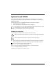
System board D1859 Your system board is available in different configuration levels. Depending on the configuration chosen, some of the hardware components described may not be available on your system board. Additional information Information on the BIOS Setup and additional descriptions of the drivers are contained: ● in the readme files on your hard disk ● on the “ServerView Suite” CDs (ServerBooks and ServerSupport) i The programme Acrobat Reader must be installed to be able to open the manuals.
Important notes Important notes With the system board installed you must open the system to access the system board. How to dismantle and reassemble the system is described in the operating manual accompanying the system. Connecting cables for peripherals must be adequately shielded to avoid interference. ! Observe the safety notes in the operating manual of your system. Incorrect replacement of the lithium battery may lead to a risk of explosion.
List of features List of features Onboard features D1859-A Chipset Intel 925 Board size ATX VGA Audio / 8-channel / S/PDIF 5.1 /-/ Buzzer / int. Speaker Support -/ LAN 1 Gbit / 100 Mbit / 10 Mbit / LAN ASF / AOL / WOL / Boot /-/ Serial ATA / ATA / RAID FireWire / / / TM / - USB 2.
List of features Internal ports (continued) D1859-A S/PDIF 5.1 (digital Audio)* OUT / IN -/- Audio Input - Front panel Audio (headphone, microphone, AC97) - TM IEEE 1394 connector* (FireWire ) - USB Ports* (2.0, ~480 Mbit/s) 4 Serial Ports* (RS232, FIFO, 16550 compatible) Fan Connectors PSU** / CPU / AUX1 / AUX2 1 / 1 /1 / 1 SMBus Connector* (Case Temperature) 1 Cover monitoring* (Casing open) 1 BTX (24-pin) / ATX12V (4-pin) power supply 1/1 External ports VGA 1 Audio Mic.
Brief instructions on installing system board Brief instructions on installing system board If you have purchased a separate system board, you can install the system board in your system in accordance with the following brief instructions. The activities described here assume a basic knowledge of servers and cannot be carried out by a layperson. If you are not sure whether you have the necessary specialised knowledge, then leave this work to an expert.
Brief instructions on installing system board ► Should no suitable connection field be provided in the case, then you must install the connection field (1) provided. Ensure the plate is aligned properly so that the connections are suitable for the system board later. ► Set the system board on the edge on which the connection field is located (2) and then insert the board in the case (3).
Interfaces and connectors 1 Channel B Channel A 2 3 4 16 5 15 6 7 slot 4 slot 2 slot 3 slot 1 PCI Express x8 PCI 1 3 PCI Express x1 4 8 SATA PCI 2 1 2 PCI 3 BIOS PCI 4 PCI 5 Battery 14 13 12 10 9 1 CPU fan (F1) 2 PC98 10 Intrusion 3 Floppy disk drive 11 I C bus (SMB1) 4 Front panel 12 Fan connector (F3) 5 Extended HD-LED 13 USB1/2 6 IDE primary (IDE1/2) 14 USB3/4 7 ATX power 24pin (PWR1) 15 TPM jumper (optional) 8 Serial ATA 1-4 16 ATX power 4pin (PWR2)
External ports External ports 1 8 2 7 3 6 5 4 1 PS/2 mouse port 5 VGA port 2 Parallel port/printer 6 Serial interface COM1 3 LAN connector (10/100/1000 Mbit/s) 7 USB1 connector 4 USB0 connector 8 PS/2 keyboard board LAN connector The system board is optionally equipped with the Broadcom BCM5751 LAN controller. This LAN controller supports the transfer rates 10 Mbit/s, 100 Mbit/s and 1000 Mbit/s.
Internal ports and connectors Internal ports and connectors The positions of the internal ports and connectors are shown on the Cover. Additional information on some ports is also provided here. Hard disk connection If you have connected hard disks to serial ATA (one hard disk is possible per serial ATA connection), you must configure the respective settings in the BIOS Setup (further information you can find in the BIOS Setup manual).
Pin assignment of internal ports Pin assignment of internal ports The pin assignment of some internal connections is shown in English in the following. i Some of the following connectors may be optional! Front panel 1) Message LED Power On HD-LED LED 2) Power On/Off Watch the poling of the LEDs. The positive pole of the connection cables is often indicated with a coloured wire.
Pin assignment of internal ports IDE/ATA interface 2 1 Pin Signal Pin Signal 1 3 5 7 9 11 13 15 17 19 21 23 25 27 29 31 33 35 37 39 Reset drive (low asserted) Data 7 (high asserted) Data 6 (high asserted) Data 5 (high asserted) Data 4 (high asserted) Data 3 (high asserted) Data 2 (high asserted) Data 1 (high asserted) Data 0 (high asserted) GND DRQ (high asserted) I/O write (low asserted) I/O read (low asserted) I/O ready (low asserted) DAK (low asserted) IRQ (high asserted) ADR 1 (high asserted) AD
Pin assignment of internal ports USB - dual channel 2 11 12 Pin Signal Pin Signal 1 Key 2 3 5 7 9 11 VCC 1 or 3 Data negative 1 or 3 Data positive 1 or 3 GND Key 4 6 8 10 12 Chipcardreader on or not connected VCC 2 or 4 Data negative 2 or 4 Data positive 2 or 4 GND not connected Fan 12 1 1 Pin Signal 1 2 3 4 GND +12 V Fan sense Fan Control D1859 (Econel 50)
Pin assignment of internal ports Floppy interface 1 Pin Signal Pin Signal 1 2 3 4 5 6 7 8 9 10 GND FDHDIN (low asserted) GND not connected Key not connected GND Index (low asserted) GND Motor A Enable (low asserted) GND Drive B Select (low asserted) GND Drive A Select (low asserted) GND 18 19 20 21 22 23 24 25 26 27 Step DIR (low asserted) GND Step Pulse (low asserted) GND Write Data (low asserted) GND Write Enable (low asserted) GND Track 0 (low asserted) GND 28 29 Write Protect (low asserted) G
Pin assignment of internal ports 2 LCD display 1 Pin Signal Pin Signal 1 2 3 4 5 6 SMB CLK GND SMB DATA GND Key RFU Reserved for Future use LAN Active Icon 8 9 10 11 12 13 LAN Link Icon Harddisk Action Icon BMC Alert Icon Message Icon Sleep Icon Power Icon 14 P3V3P_DUAL 7 Intrusion 14 1 Pin Signal 1 2 3 GND Case open (low asserted) Intrusion switch present (low asserted) D1859 (Econel 50)
Pin assignment of internal ports 1 Power supply BTX (ATX compatible) 13 Pin Signal Pin Signal 1 2 3 4 5 6 7 8 9 10 11 12 +3.3 V (P3V3P) +3.3 V (P3V3P) GND +5V (VCC) GND +5V (VCC) GND Powergood (high asserted) +5 V Auxiliary (VCC Aux) +12 V (P12VP) +12 V (P12VP) 13 14 15 16 17 18 19 20 21 22 23 24 +3.
Pin assignment of internal ports 1 Power supply control (System monitoring) 16 Pin Signal 1 2 4 Power Guard Control PS FAN Control PS FAN Sense D1859 (Econel 50)
Jumper settings The positions of the jumpers are shown on page "Cover". Setting via control-panel plug connector A 1 2 Pin pair A inserted = Skipping system and BIOS Setup password B 1 2 Pin pair B inserted = System BIOS recovery C 1 2 Pin pair C inserted = factory setting i Please pay attention on the exact position of the pin pairs! Skipping system and BIOS Setup password - pinpair A Pinpair A enables skipping the system and BIOS Setup password.
Add-on modules / Upgrading ! Exit energy-saving mode, switch off the system and remove the power plug from the mains outlet, before carrying out any of the procedures described in this chapter! Even when you have run down the device, parts of the device (e.g. memory modules, PCI extension boards) are still energised. Installing and removing processors Technical data ● Intel Pentium 4 with 800 MHz front side bus (FSB) in the LGA775 design.
Add-on modules / Upgrading a ► Insert the new processor in the socket so that the marking of the processor is aligned with the marking on the socket (a). 1 2 3 ► Fold down the frame (1). ► Press the lever downward (2) until it is hooked in again (3).
Add-on modules / Upgrading Mounting heat sink i Use only the heat sink supplied with your system! Be sure to use heat conducting material between the processor and the heat sink. If a heat conducting pad (rubber-like foil) is already applied to the heat sink, then use it. Otherwise you must apply a very thin layer of heat conducting paste. Heat conducting pads can only be used once. If you remove the heat sink, you must clean it and apply new heat conducting paste before you remount it.
Add-on modules / Upgrading Upgrading main memory Technical data Technology: DDR2 400 / DDR2 533 unbuffered DIMM modules 184-Pin; 1.8 V; 64 Bit, with ECC Size: 256 Mbytes to 4 Gbytes DDR2 Granularity: 256, 512 or 1024 Mbyte for one socket A current list of the memory modules recommended for this system board is available on the Internet at: www.fujitsu-siemens.com. At least one memory module must be installed. Memory modules with different memory capacities can be combined.
Add-on modules / Upgrading Installing a memory module 2 2 ► Push the holders on each side of the memory slot outwards. ► Insert the memory module into the location (1). ► At the same time flip the lateral holders upwards until the memory module snaps in place (2). Removing a memory module 1 1 ► Push the clips on the right and left of the memory slot outward (1). ► Pull the memory module out of the memory slot (2).
Add-on modules / Upgrading Adding PCI Express cards The PCI Express x8 slot is intended for graphics cards, and the PCI Express x1 slot for PCI Express x1 cards. Adding PCI cards Technical data: 32 bit / 33 MHz PCI slots 3.3 V supply voltage (PCI 2.3 compliant) 3.3 V auxiliary voltage PCI bus interrupts - Selecting correct PCI slot i To achieve optimum stability, performance and compatibility, avoid the multiple use of ISA IRQs or PCI IRQ Lines (IRQ sharing).
Add-on modules / Upgrading Multifunctional expansion cards or expansion cards with integrated PCI-PCI bridge: These expansion cards require up to four PCI interrupts: INT A, INT B, INT C, INT D. How many and which of these interrupts are used is specified in the documentation provided with the card.
Add-on modules / Upgrading Replacing the lithium battery In order to permanently save the system information, a lithium battery is installed to provide the CMOS-memory with a current. A corresponding error message notifies the user when the charge is too low or the battery is empty. The lithium battery must then be replaced.
Add-on modules / Upgrading BIOS update When should a BIOS update be carried out? Fujitsu Siemens Computers makes new BIOS versions available to ensure compatibility to new operating systems, new software or new hardware. In addition, new BIOS functions can also be integrated. A BIOS update should always also be carried out when a problem exists that cannot be solved with new drivers or new software. Where can I obtain BIOS updates? The BIOS updates are available on the Internet at www.fujitsu-siemens.
Add-on modules / Upgrading BIOS Recovery - Recovering System BIOS i All BIOS settings are reset to the default values. ► Open the casing as described in the operating manual. ► On the system board set the jumper to the appropriate setting to restore the system BIOS (see chapter "Jumper settings"). ► Close the casing as described in the operating manual. ► Insert a BIOS update floppy disk and start the server. ► Note the signals issued from the loudspeaker.
Add-on modules / Upgrading Microcode Update What is a microcode update? As there are no drivers for processors, Intel offers the possibility from the P6 family (Pentium Pro) on to update the command set (microcode) of the processor. This enables minor errors to be corrected and the performance to be increased. To guarantee the best possible performance and error-free operation, Intel recommends updating the microcode for every new processor.
Annex Annex System board Revision and BIOS Version System board Revision The revision status of the system board exactly identifies which system board you have. It is indicated on a sticker on the edge of the system board: D1859-A10 GS 1 05618476 Example System board revision BIOS version The BIOS version can be displayed in the BIOS Setup. ► Press F2 during booting to open the BIOS Setup. ► Press F1 . The BIOS version is specified on the displayed information page under the entry BIOS Release.
Annex Electrical Properties Loadability for connections and fuses i Make sure that the connected devices do not overload the connections. Fuse no. Fuse Connection Maximum loadability 1 750 mA 2 2000 mA 3 2000 mA Keyboard Mouse USB port 1 USB port 2 USB port 3 USB port 4 USB port 5 USB port 6 USB port 7 USB port 8 Not specified Not specified 500 mA 500 mA 500 mA 500 mA 500 mA 500 mA 500 mA 500 mA The fuses on this system board can be used several times (polyfuses).
Error messages Error messages This chapter contains error messages generated by the system board. Available CPUs do not support the same bus frequency - System halted! Memory type mixing detected Non Fujitsu Siemens Memory Module detected - Warranty void There are more than 32 RDRAM devices in the system Check whether the system configuration has changed. If necessary, correct the settings.
Error messages DMA test failed EISA CMOS not writable Extended RAM Failed at offset: nnnn Extended RAM Failed at address line: nnnn Failing Bits: nnnn Fail-Safe Timer NMI failed Multiple-bit ECC error occurred Memory decreased in size Memory size found by POST differed from EISA CMOS Single-bit ECC error occurred Software NMI failed System memory exceeds the CPU’s caching limit System RAM Failed at offset: nnnn Shadow RAM Failed at offset: nnnn Switch the device off and on again.
Error messages Keyboard error nn nn Stuck Key Release the key on the keyboard (nn is the hexadecimal code for the key). Missing or invalid NVRAM token Switch the device off and on again. If the message is still displayed, please contact your sales outlet or customer service centre. Monitor type does not match CMOS - RUN SETUP Correct the entry for the monitor type in the Main menu of the BIOS Setup.
Error messages System Management Configuration changed or Problem occurred A system fan or system sensor has failed. Check the hardware operation. System timer error Switch the device off and on again. If the message is still displayed, please contact your sales outlet or customer service centre. Uncorrectable ECC DRAM error DRAM Parity error Unknown PCI error Switch the device off and on again. If the message is still displayed, please contact your sales outlet or customer service centre.
Glossary The technical terms and abbreviations given below represent only a selection of the full list of common technical terms and abbreviations. Not all technical terms and abbreviations listed here are valid for the described system board.
Information on this document On April 1, 2009, Fujitsu became the sole owner of Fujitsu Siemens Computers. This new subsidiary of Fujitsu has been renamed Fujitsu Technology Solutions. This document from the document archive refers to a product version which was released a considerable time ago or which is no longer marketed. Please note that all company references and copyrights in this document have been legally transferred to Fujitsu Technology Solutions.