C156-E228-02EN MCM3064SS, MCM3130SS MCP3064SS, MCP3130SS OPTICAL DISK DRIVES PRODUCT MANUAL
FOR SAFE OPERATION Handling of This Manual This manual contains important information for using this product. Read thoroughly before using the product. Use this product only after thoroughly reading and understanding especially the section "Important Alert Items" in this manual. Keep this manual handy, and keep it carefully. FUJITSU makes every effort to prevent users and bystanders from being injured or from suffering damage to their property. Use the product according to this manual.
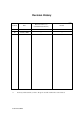
Revision History (1/1) Edition Date Revised section (*1) (Added/Deleted/Altered) Details 01 March, 2002 — — 02 January, 2004 — — *1 Section(s) with asterisk (*) refer to the previous edition when those were deleted.
This page is intentionally left blank.
Preface This manual describes the MCM3064SS, MCM3130SS, MCP3064SS and MCP3130SS 3.5-inch optical disk drives. This manual provides an overview of the above optical disk drives, and explains their specifications, the requirements and procedures for installing them in a system, and how to clean them. The manual is intended for users who have a basic understanding of optical disk drives and their use in computer systems.
Preface • Notes on removing the installed drive Chapter 5 Operation and Cleaning This chapter describes how to operate and clean MCM3064SS, MCM3130SS, MCP3064SS and MCP3130SS optical disk drives. This chapter also describes how to operate and clean optical disk cartridges. Chapter 6 Diagnostics and Maintenance This chapter describes the self-diagnostics functions and maintenance of the MCM3064SS, MCM3130SS, MCP3064SS and MCP3130SS optical disk drives.
Preface Conventions for Alert Messages This manual uses the following conventions to show the alert messages. An alert message consists of an alert signal and alert statements. The alert signal consists of an alert symbol and a signal word or just a signal word. The following are the alert signals and their meanings: This indicates a hazardous situation likely to result in serious personal injury if the user does not perform the procedure correctly.
This page is intentionally left blank
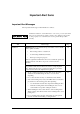
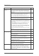
Important Alert Items Important Alert Messages The important alert messages in this manual are as follows: A hazardous situation could result in minor or moderate personal injury if the user does not perform the procedure correctly. Also, damage to the product or other property, may occur if the user does not perform the procedure correctly.
Important Alert Items Task Installation Alert message Page Before moving the drive, remove the optical disk cartridge. If the drive is moved with the optical disk cartridge loaded in it, the head may move back and forth in the drive to damage the head or disk and reading the data may fail 4-2 1) The user must not change the settings of terminals not described in this section. The terminals must remain as set when shipped. 4-5 2) Do not change terminal settings when the power is on.
MANUAL ORGANIZATION OPTICAL DISK DRIVES 1. GENERAL DESCRIPTION PRODUCT MANUAL 2. SPECIFICATIONS (C156-E228) 3. INSTALLATION REQUIREMENTS 4. HOST INTERFACE 5. OPERATION AND CLEANING 6. DIAGNOSTICS AND MAINTENANCE OPTICAL DISK DRIVES 1. COMMAND PROCESSING SCSI Logical Specifications 2. DATA BUFFER MANAGEMENT (C156-E092) 3. COMMAND SPECIFICATIONS 4. SENSE DATA AND ERROR RECOVERY 5. SCSI MESSAGES 6.
REFERENCED STANDARDS The product specifications and functions described in this manual conform to the following standards: Specification (document) number Name Concerned organization ANSI X3.131-1986 American National Standard for Information System - small ComputerSystem Interface (SCSI) American National Standards Institute (ANSI) ANSI X3.
Contents CHAPTER 1 General Description................................................................ 1-1 1.1 Features..................................................................................................... 1-1 1.1.1 1.1.2 1.1.3 1.1.4 1.1.5 Performance and Functions................................................................. 1-1 Reliability............................................................................................ 1-3 Maintainability/operability .......................
Contents 3.1.1 3.1.2 3.1.3 3.1.4 3.1.5 Temperature measurement points........................................................ 3-1 Temperature requirements................................................................... 3-2 Temperature rise.................................................................................. 3-3 Air flow ............................................................................................... 3-4 Air cleanliness .........................................................
Contents CHAPTER 5 Operation and Cleaning ......................................................... 5-1 5.1 Operation of Optical Disk Drive .............................................................. 5-1 5.1.1 5.1.2 5.1.3 5.1.4 Appearance of optical disk drive ........................................................ 5-1 Precautions .......................................................................................... 5-2 Inserting an optical disk cartridge..........................................
Contents 7.4 Electrical Requirements..........................................................................7-11 7.4.1 7.4.2 7.4.3 SCSI interface....................................................................................7-11 Power supply for terminating resistor ...............................................7-12 Signal driving conditions...................................................................7-13 7.5 Timing Rule .......................................................................
Contents Illustrations FIGURES C156-E228-02EN Figure 1.1 Figure 1.2 Figure 1.3 Figure 1.4 The optical disk drive (with panel) ............................................. 1-6 The optical disk drive (without panel)........................................ 1-6 Configuration of optical disk drive............................................. 1-7 Block diagram of the control circuit section............................... 1-9 Figure 2.1 Figure 2.2 Figure 2.3 Optical disk cartridge .........................
Contents xiv Figure 5.2 Figure 5.3 Figure 5.4 Figure 5.5 Figure 5.6 Figure 5.7 Figure 5.8 Figure 5.9 Inserting an optical disk cartridge...............................................5-3 Removing an optical disk cartridge ............................................5-5 Appearance of optical disk cartridge ..........................................5-7 Write protect tab..........................................................................5-8 Opening a shutter ...........................................
Contents TABLES C156-E228-02EN Table 2.1 Table 2.2 Table 2.3 Table 2.4 Table 2.5 Representative model names and order numbers ....................... 2-1 Specifications.............................................................................. 2-2 Environmental and power requirements .................................... 2-4 Recommended optical disk cartridges ........................................ 2-7 Disk specifications ....................................................................
This page is intentionally left blank.
CHAPTER 1 General Description 1.1 Features 1.2 Configuration of Optical Disk Drive This chapter describes the features and configuration of the MCM3064SS, MCM3130SS, MCP3064SS and MCP3130SS optical disk drives. As successors to the MCE3064SS and MCE3130SS optical disk drives, the MCM3064SS, MCM3130SS, MCP3064SS and MCP3130SS optical disk drives (hereafter called the optical disk drives) achieve high-speed operation while maintaining compatibility with the MCE3064SS and MCE3130SS.
General Description (3) High-speed mean seek time This drive features a linear voice coil motor for high-speed head positioning. The average seek time per 1,000 random seeks is 23 ms. (However, this does not include command overhead or address check.) (4) Compatibility with international standards (media interchangeability) The MCM3130SS and MCP3130SS optical disk drives support the use of 90mm(3.5-inch) optical disks in the 1.
1.1 Features 1.1.2 Reliability (1) Mean time between failures (MTBF) The mean time between failures (MTBF) for this optical disk drive is 120,000 hours or more. (2) Enhanced error recovery If an error occurs on the optical disk drive, the system executes appropriate retry processing to recover from it. This drive features enhanced Reed-Solomon error correction code (ECC) to assure error-free operation.
General Description (3) Safety standards The optical disk drive is certified under the following standards: • UL1950 (U.S. safety standard) • CDRH (U.S. laser standard) (Class 1) • CSA C22.2 No.
1.1 Features (4) Read-ahead cache feature The read-ahead cache feature enables high-speed sequential data access as follows: After executing a command to read data from the disk, the drive automatically reads the next data block and stores it in the data buffer (pre-reading). If the next command requests this data, the drive can transfer data from the buffer without accessing the disk again.
General Description 1.2 Configuration of Optical Disk Drive 1.2.1 Appearance Figures 1.1 and 1.2 show the optical disk drive. Figure 1.1 The optical disk drive (with panel) Figure 1.
1.2 Configuration of Optical Disk Drive 1.2.2 Configuration Figure 1.3 shows the configuration of the optical disk drive. The optical disk drive consists of a mechanical section, a fixed optics section, a control circuit section, and an actuator. The mechanical section includes the spindle motor, actuator section, bias magnet, and cartridge holder vertical motion mechanism. The fixed optics section consists of the optical components, position detector, and LD controller.
General Description (3) Actuator section The actuator section consists of a focus actuator and a tracking actuator. The former focuses a laser beam on the surface of an optical disk while the latter moves the beam spot along the radius, on the surface of an optical disk (seek operation). The actuator section is directly driven by a linear voice coil motor. The tracking actuator is based on the pulse-width modulation (PWM) system and realizes low power consumption and high-speed access.
1.2 Configuration of Optical Disk Drive SCSI controller circuit section MPU ODC DSP User Logic LSI i/f SCSI I/F Mecha section Head section Laser Diode Photo Diode APC Amp LPC Amp Head Amp F-ROM D-RAM Driver circuit section Read Amp Power Amp Filter Sensor Motor Driver Actuator section Focus Act. Track Act. Spindle Motor Temperature Sensor Bias Coil Eject Motor Cartridge Sensor Figure 1.
This page is intentionally left blank.
CHAPTER 2 Specifications 2.1 Specifications of Optical Disk Drives 2.2 Specifications of Optical Disk Cartridges 2.3 Defect Management This chapter provides the specifications of the optical disk drives and the optical disk cartridge. 2.1 Specifications of Optical Disk Drives 2.1.1 Catalog and order numbers Table 2.1 lists the model names (catalog numbers) and order numbers of optical disk drives. Table 2.1 Representative model names and order numbers Model name (catalog number) Order No.
Specifications 2.1.2 Specifications of drives Table 2.2 lists the specifications of MCM3064SS, MCM3130SS, MCP3064SS and MCP3130SS optical disk drives. Table 2.2 Specifications (1 of 2) [MCM3064SS, MCM3130SS, MCP3064SS and MCP3130SS] Item Optical disk media 230 MB media 540 MB media 640 MB media 1.3 GB media (*7) 181 MB 325 MB 819 MB 818 MB 1.688 GB Formatted 128 MB 230 MB 538 MB 643 MB 1.
2.1 Specifications of Optical Disk Drives Table 2.2 Specifications (2 of 2) Item Specifications Optical disk media 128 MB media 230 MB media Data buffer 2 MB Error correction (*6) Correctable up to 8-byte/interleave Bit error rate: 10-12 or less 540 MB media 640 MB media 1.3 GB media (*7) *1 The number of user tracks indicates the maximum user zone which includes the spare area and slipping area.
Specifications 2.1.3 Environmental and power requirements Table 2.3 lists the environmental and power requirements. Table 2.3 Environmental and power requirements (1 of 2) Item Specification Power requirements Average +5 VDC±5% (*1), 1.2A (2.7A max) Ripple requirement 100mV pp (DC-1 MHz) Power Ready 3.9 W (typ) (*2) consumption Random seek, read or write 6.1 W (typ) (*2) (Average) Power save mode 3.9 W (typ) (*2) 2.0 W (typ) (*2) 1.2 W (typ) (*2) 1.
2.1 Specifications of Optical Disk Drives Table 2.3 Environmental and power requirements (2 of 2) Item Vibration/ shock Operating Idle No cartridge, power ON Altitude Ambient cleanliness Specification 2 3.92 m/s {0.4 G} (5 to 500 Hz, Sine Sweep) 2 Shock 19.6 m/s {2 G} (10 ms, Half Sine Pulse) 2 Shock 9.8 m/s {1.
Specifications 2.1.5 Reliability (1) Mean time between failures (MTBF) The MTBF is 120,000 hours or more. Failures due to disk errors are not included. Conditions • Power-on time: 200 hours/month or less • LD-on time: 20% or less of power-on time • Ambient temperature: 25°C Note: The MTBF is defined as follows: Total operating time in all fields (hours) MTBF = Number of device failure in all fields 1) Operating time is the total time in which power is supplied.
2.2 Specifications of Optical Disk Cartridges 2.2 Specifications of Optical Disk Cartridges 2.2.1 Recommended optical disk cartridges Optical disk cartridges basically comply with the ISO/IEC 10090 standard for 128 MB capacity, ISO/IEC 13963 standard for the 230 MB capacity, and ISO/IEC 15041 standard for the 540 and 640 MB capacity. Table 2.4 shows the specifications of the optical disk cartridges recommended for this optical disk drive.
Specifications 2.2.2 Appearance Figure 2.1 shows an optical disk cartridge. The names of the components of an optical disk cartridge are also shown. (a) Shutter closed (2) Shutter (1) Cartridge case (3) Write protect tab Figure 2.1 Optical disk cartridge (1 of 2) (b) Shutter open (4) Disk (5) Hub Figure 2.
2.2 Specifications of Optical Disk Cartridges The following explains the components of the optical disk cartridge shown in Figure 2.1. 1) Cartridge case The disk housing is provided to protect the disk from damage when handling it, and facilitates replacement of the disk. The cartridge case has a label and a write protect tab on it. 2) Shutter The shutter protects the disk from contamination. This metallic door opens when the cartridge is inserted into the optical disk drive.
Specifications 2.2.3 Specifications of disk Table 2.5 lists the disk specifications. Table 2.
2.3 Defect Management 2.3 Defect Management 2.3.1 Defect management schematic diagram Defective sectors on the disk must be replaced with good sectors in accordance with the defect management scheme as follows: Sectors found defective during surface inspection are handled using a sector slipping algorithm. Sectors found defective after initialization are replaced using a linear replacement algorithm. Figure 2.2 shows the sector slipping and linear replacement algorithms.
Specifications Figure 2.
CHAPTER 3 Installation Requirements 3.1 Environmental Requirements 3.2 Mounting Requirements 3.3 Power supply Requirements 3.4 Connection Requirement This chapter describes environmental, mounting, power supply, and connection requirements. 3.1 Environmental Requirements The optical disk drive must be installed in an environment complying with the ambient environmental requirements defined in Section 2.1.3. 3.1.
Installation Requirements (b) IC (controller, read Amp) IC (controller) IC (read Am p) Figure 3.1 Surface temperature measurement point (2 of 2) 3.1.2 Temperature requirements Table 3.1 shows the temperature requirement at the measurement point shown in Figure 3.1. Table 3.1 Temperature requirements at measurement points Measurement point Inside the cartridge Maximum allowable surface temperature 55°C (*1) IC (controller) surface 85°C IC (read Amp.
3.1 Environmental Requirements 3) Cut off part of the wall surrounding the optical disk (disk outer wall) as shown in Figure 3.1. At this point, cut off a section 5 to 10 mm in width from the disk outer wall. 4) Using an adhesive agent, affix the tip of the thermocouple to the opening of the disk outer wall. 5) Pass the thermocouple through the hole in the cartridge and reassemble the cartridge. Using an adhesive agent, etc., fill any gap between the hole and the thermocouple.
Installation Requirements 3.1.4 Air flow It is recommended that this optical disk drive be installed in a fanless cabinet. However, if the power supply is included in the same cabinet, the “Temperature Conditions” in 3.1.2 must be met. Furthermore, we recommend that the speed of air drawing in by the device from the left side of the cartridge loading slot in the front panel dose not exceed 0.3m/s for MCM3064SS or MCM3130SS, and dose not exceed 0.1m/s for MCP3064SS or MCP3130SS.
3.2 Mounting Requirements Figure 3.
Installation Requirements Panel Below 3.3 Position after a cartridge is loaded Position when loading a cartridge Below 7.8 Center of a cartridge when loaded Bottom of the frame A-A Section Figure 3.2 Outer dimensions (2 of 2) Notes 3-6 1. Fujitsu recommends using the dimensions indicated by asterisks in the above figure for the size of the panel opening. 2. If the specified dimensions are not used, the MO disks might be damaged when a cartridge is loaded.
3.2 Mounting Requirements Figure 3.
Installation Requirements Oblong hole: 2±0.1 (width) × 2.5±0.1 (length) (Width of C 0.5) (Stroke for the switch) Details of C part Details on D part Figure 3.
3.2 Mounting Requirements Figure 3.
Installation Requirements 3.2.2 Installation direction Figure 3.4 shows the permissible installation directions for the optical disk drive. The mounting angle tolerance must be within -5° to 10° relative to the horizontal plane. (-) shows that the cartridge insertion slot faces downward. Disk insertion slot Eject button/Busy LED Horizontal Manual eject hole Vertical (Two orientations) Figure 3.
3.2 Mounting Requirements 3.2.3 Center of gravity Figure 3.5 shows the center of gravity of the optical disk drive. Figure 3.
Installation Requirements 3.2.4 Precautions on mounting (1) Mounting frame structure and clearance a) For vibration resistance and heat dissipation, mount this optical disk drive using a frame having an embossed structure shown in Figure 3.6 or a similar structure providing an equivalent function. b) A mounting screw must have an inward projection (entry depth) of 3 mm or less from the outer surface of the mounting frame of the optical disk drive as shown in Figure 3.6.
3.2 Mounting Requirements (2) Checking the panel function There must not be any deformation in the panel after the optical disk drive is installed in a cabinet. Make sure that the door of the disk insertion slot closes from any location with the drive installed in the cabinet. (3) Service areas Figure 3.7 shows the locations that need to be accessed for installation, and after installation is carried out. Figure 3.
Installation Requirements The optical disk drive can be mounted in a 120 mm (5 inch) device bay of the PC chassis using either a metal frame or a plastic (nonconductive material) frame. If a plastic frame is used, the personal computer's FG and the optical disk drive's FG are not shorted. Consequently, the static electricity tolerance is inferior to that realized when a metal frame is used. Fujitsu recommends using a metal frame.
3.3 Power Supply Requirements Figure 3.9 Power on/off sequence (1) b) In a system which does not use the terminating resistor power supply signal (TERMPWR) of the SCSI bus, the requirements for +5 VDC given in Figure 3.10 must be satisfied between the drive and the SCSI device with the terminating resistor circuit. 4.75V 4.75V 0.5V Figure 3.10 c) 0.
Installation Requirements (4) Power supply to SCSI terminating resistor If the power for the terminating resistor is supplied from the drive to other SCSI devices through the SCSI bus, the current-carrying capacity of the +5 VDC power supply line to the optical disk drive must be designed with consideration of an increase of up to 900 mA. Select a method of power supply to the drive in accordance with the setting terminal of the optical disk drive. See Subsection 4.3.3.
3.4 Connection Requirement 3.4 Connection Requirement 3.4.1 Connectors and terminals This drive is equipped with the connectors and terminals shown below for external connection. Figure 3.13 shows their locations. Power supply connector SCSI connector External operator panel terminal (CNH2) Figure 3.
Installation Requirements (1) Power supply connector Figure 3.14 shows the shape and pin assignment of the DC power supply input connector. Figure 3.14 1 +12 VDC or N.C. 2 +12 VDC RETURN (GND) or N.C. 3 +5 VDC RETURN (GND) 4 +5 VDC Power supply connector (2) SCSI connector The connector for the SCSI bus is an unshielded standard connector with two rows of 25 pins on 2.54 mm centers. See Chapter 7 for details on the electrical requirements of the interface signals.
3.4 Connection Requirement 3.4.2 Cable connection requirements Figure 3.15 shows the cable connection mode between the drive, host system, and power supply unit. Table 3.3 lists recommended components for the connection. Figure 3.
Installation Requirements Table 3.3 Recommended components for connection Category Name SCSI cable Power supply cable External operator panel Model Manufacturer Symbol in Figure 3.15 S01 Cable socket (closed-end type) FCN-707B050-AU/B Fujitsu Ltd. Cable socket (through-end type) FCN-707B050-AU/O Fujitsu Ltd. Signal cable UL20184LT25PX28AWG Hitachi Cable, Ltd.
3.4 Connection Requirement Provide switches and LEDs (required for the system) on the external operator panel. See the recommended circuit shown in Figure 3.21. A signal which is not set on the external operator panel connected to CNH2 must be set using SW1. The SW1, and CNH1 corresponding to the signal set on the external operator panel must be set to OFF position. For details, see Subsection 4.3.1. Figure 3.17 shows the external operator panel connector and Table 3.
Installation Requirements Figure 3.17 External operator panel interface connector Table 3.4 External operator panel interface Signal Pin Reference setting signal SCSI-ID 4 2 SW1-01 Equivalent to ON position of SW1-01 by shorting with 0 V. SCSI-ID 2 4 SW1-02 Equivalent to ON position of SW1-02 by shorting with 0 V. SCSI-ID 1 6 SW1-03 Equivalent to ON position of SW1-03 by shorting with 0 V. Device type mode 9 SW1-06 Equivalent to ON position of SW1-06 by shorting with 0 V. See 3.4.
3.4 Connection Requirement 3.4.4 External operator panel settings (CNH2) (1) Device type mode Table 3.5 shows the device type settings which are returned when the INQUIRY command is issued to the optical disk drive. Table 3.5 Device type mode setting Device Type CNH 2/Pin 9 - GND X'07' (Optical memory device) Short X'00' (Direct access device) Open * * Setting when shipped (2) Verify mode The default setting of the verify function is specified.
Installation Requirements (3) SCSI type 0 The command specification and message specification are specified. The SCSI-1 specification is compatible with that of the old unit (M2511A). Table 3.7 shows the command and message specification settings. Table 3.
CHAPTER 4 Installation 4.1 4.2 4.3 4.4 4.5 4.6 4.7 Notes on Drive Handling Connection Modes Settings Mounting Cable Connections Operation Confirmation and Preparation for Use after Installation Dismounting Drive This chapter describes notes on handling the drives, connection modes, settings, mounting the drives, cable connections, and operation confirmation and preparation for use after installation, and notes on demounting the drives. 4.
Installation b) Use care to avoid exerting excessive pressure on the unit when removing the cushions. c) Use care to avoid exerting excessive pressure on the PCA surface and interface connectors when removing the drive from the antistatic bag. d) If the temperature difference between installation locations is 10 degrees or more, leave the drive in the new location for at least two hours before unpackaging it.
4.1 Notes on Drive Handling Drive Drive Desiccant Ejecting Jig Holder Desiccant Ejecting Jig Holder Packing box for each individual unit Label Box Label Figure 4.1 Individual packaging style Carton of packing boxes Figure 4.2 Gathered packaging style (5) Transportation a) Transport the package with the UP sign upward. b) After unpacking, minimize the transportation distance and use cushions to avoid shock and vibration. Transport the drive in one of the orientations described in Subsection 3.
Installation 4.2 Connection Modes Figure 4.3 shows examples of connections between the host system and the optical disk drive. Up to eight devices including the host adapter, optical disk drive, and other SCSI equipment can be connected to the SCSI bus in arbitrary combinations. Install a terminating resistor on the SCSI devices connected to either end of the SCSI cable. See Section 3.4 for the cable connection requirements and power cable connections.
4.3 Settings (c) Connecting more than one optical disk drive (multi-host) Figure 4.3 SCSI bus connection modes (2 of 2) 4.3 Settings Before installing the drive in the system, set the following setting terminal, setting switches, and SCSI terminating resistors: • Setting terminal : CNH1 • Setting switches : SW1 Figure 4.4 shows the positions of the setting terminal and switch. 1) The user must not change the settings of terminals not described in this section.
Installation Figure 4.
4.3 Settings 4.3.1 Setting switches (SW1) Figure 4.5 shows the types of switches and their settings when the drive was shipped. • SW1 SCSI ID OFF 1 SCSI ID 2 SCSI ID 3 4 5 6 7 8 Setting switch Board Switch number SW1 Signal name At shipment 01 02 03 SCSI ID OFF OFF OFF 04 SCSI data bus parity check ON 05 Write cache mode OFF 06 Device type mode ON 07 Spindle automatic stop mode ON 08 Factory test mode (user setting inhibited) OFF Figure 4.
Installation (1) SCSI ID Table 4.1 shows the SCSI ID settings of the drive. Table 4.1 SCSI ID setting (SW1) SCSI ID SW1-01 SW1-02 SW1-03 0 (*1) OFF OFF OFF 1 OFF OFF ON 2 OFF ON OFF 3 OFF ON ON 4 ON OFF OFF 5 ON OFF ON 6 ON ON OFF 7 ON ON ON *1 Setting when shipped 1) Each SCSI device connected to the same SCSI bus must have a unique SCSI ID.
4.3 Settings (3) Write cache mode The write cache mode can be set. The write cache mode can also be enabled or disabled by the MODE SELECT command. When the write cache mode is enabled, the cache control page is added to the code page of the mode parameter even if the SCSI-1 is set. Table 4.3 shows the settings of the write cache mode. Table 4.3 Write cache mode setting Write cache mode SW1-05 Write cache is enabled at executing the WRITE/WRITE AND VERIFY command.
Installation The access supervision time from the host is about 33 minutes as the default. However, it can be changed by the MODE SELECT command. The spindle auto stop mode can also be changed by the MODE SELECT command. Table 4.5 shows spindle auto stop mode setting. Table 4.5 Spindle automatic stop mode setting Spindle auto stop SW1-07 The spindle motor automatically stops. ON (*1) The spindle motor does not automatically stop.
4.3 Settings 4.3.3 SCSI terminating resistor mode Enabling or disabling the SCSI terminating resistor, module on the PCA can be set. When the drive positions at other than the end of the SCSI bus, the SCSI terminating resistor should be disabled. Table 4.7 shows the SCSI terminating resistor mode setting. Table 4.7 SCSI terminating resistor mode (CNH1) SCSI terminating resistor mode CNH 1 05-06 SCSI terminating resistor module on the PCA is enabled.
Installation 4.4 Mounting 4.4.1 Checks before mounting the drive Before mounting the optical disk drive in the system cabinet, check whether the setting switches and terminals are set correctly. Table 4.8 shows the checklist. Table 4.
4.5 Cable Connections 4.4.2 Mounting procedure How the drive is mounted depends on the system cabinet structure. Determine the mounting procedure in consideration of the requirements of each system. This section contains the general mounting procedure and check items. See Section 3.2 for details on mounting drive.
Installation 4) After each cable connector is connected, secure the cable so that the cable does not touch the drive or the parts on the PCA or obstruct the flow of cooling air in the system cabinet. 1) Be careful of the insertion directions of SCSI connectors.
4.6 Operation Confirmation and Preparation for Use after Installation The BUSY LED is on while the optical disk drive is executing seek, write, or read operations. The BUSY LED is on momentarily, so it seems as if it blinked or is off. The eject motor turns once when the power is turned on so that in case the spindle motor position deviates due to shocks received by the drive during transport the position is corrected to allow the cartridge to be inserted normally.
Installation Figure 4.
4.7 Dismounting Drive (2) If processing terminates abnormally: a) If sense data has been obtained by the REQUEST SENSE command, analyze the sense data. If the error is recoverable, retry the processing. b) Check the following items for SCSI cable connection: All connectors, including other SCSI devices, are connected correctly. A terminating resistor is correctly mounted at both ends of the cable. Power is supplied to the terminating resistors correctly.
This page is intentionally left blank.
CHAPTER 5 Operation and Cleaning 5.1 Operation of Optical Disk Drive 5.2 Cleaning of Optical Disk Drive 5.3 Operation of Optical Disk Cartridge 5.4 Cleaning of Optical Disk Cartridge This chapter describes how to operate and clean the optical disk drive and an optical disk cartridge. 5.1 Operation of Optical Disk Drive The optical disk drive has automatic load and eject functions. All of the operator must do about the drive is to insert an optical disk cartridge and push the eject button.
Operation and Cleaning 1) Disk insertion slot Insert and eject an optical disk cartridge into and out of this slot. 2) Eject button & BUSY LED (indicator lamp) On this optical disk drive, the eject button serves also as the BUSY LED (indicator lamp). Eject an optical disk cartridge by pressing this button, which also goes on in green during seeking and during erasing, writing or reading of data. When ejection is disabled by an SCSI command, an optical disk cartridge cannot be taken out.
5.1 Operation of Optical Disk Drive 3. If the BUSY LED indicator lamp does not go on after a cartridge is inserted, press the eject/BUSY LED button once to eject the cartridge and insert it again. 4. Do not forcibly insert a cartridge if you have any difficulty inserting it. If you do, the drive may be damaged. In such a case, be sure to remove the cartridge once and check the insertion orientation and the face and back of the cartridge before inserting it again.
Operation and Cleaning If you insert an optical disk cartridge with the printed shutter facing upward by pressing on the rear of cartridge at the left edge, you may hear an audible click but the drive may not become READY. In such a case, press the cartridge further by pressing on the back of the cartridge from the center (somewhere near the notched section of the panel front) until the LED indication lamp goes on. If this happens, the cartridge has been normally inserted. 5.1.
5.2 Cleaning of Optical Disk Drive Figure 5.3 Removing an optical disk cartridge 5.2 Cleaning of Optical Disk Drive The drive performance may deteriorate if dust, particle or cigarette smoke deposits accumulate on the lens actuator of the drive. Clean the lens actuator periodically using following head cleaner (*1). *1 How often the lens actuator should be cleaned varies depending on the environment in which the optical disk drive has been installed.
Operation and Cleaning Device Damage: Be sure to use the dedicated head cleaner shown above. Check the state of the cleaning brush by opening the shutter of the head cleaner. If the tips of the brush bristles are spread out, the lens cannot be completely cleaned. In such a case, use a new head cleaner. 5.3 Operation of Optical Disk Cartridge 5.3.1 Appearance Figure 5.4 shows the appearance of an optical disk cartridge.
5.3 Operation of Optical Disk Cartridge (a) Shutter closed (2) Shutter (1) Cartridge case (3) Write protect tab (b) Shutter open (4) Disk (5) Hub Figure 5.
Operation and Cleaning 5.3.2 Write protect tab Move the write protect tab to enable or disable writing to an optical disk cartridge. Use a fingernail or something similar to move the write protect tab (it must be completely moved to one end because there is some play in the middle). Figure 5.5 shows where the write protect tab is located on a optical disk cartridge and how the write protect tab should be moved (see the Write Enabled and Write Disabled indications printed on the label).
5.3 Operation of Optical Disk Cartridge 5.3.3 Precautions To maintain the performance and reliability of an optical disk cartridge, keep the following points in mind when using, storing, or transporting an optical disk cartridge: (1) Using a cartridge • Do not use a cartridge in an environment where it is exposed to direct sunlight or sharp temperature changes, or high temperature or humidity. • Do not press hard, drop, or otherwise apply excessive shock or vibration to a cartridge case or shutter.
Operation and Cleaning 5.4 Cleaning the Optical Disk Cartridge You must periodically clean an optical disk cartridge because the accumulation of dust, particle, or cigarette smoke deposits on the disk lowers the performance of the cartridge. How often the cartridge should be cleaned varies depending on the environment in which the optical disk drive has been installed. Usually, clean the cartridge once every 300 hours of operation or once in two to three months. 5.4.
5.4 Cleaning the Optical Disk Cartridge (2) Precautions on use and storage of cleaning kit Keep the following in mind when using or storing the cleaning kit: • Tighten the cap after using the cleaning solution. • Do not insert a floppy disk or stack floppy disks in the setting case because a magnet is used at the disk revolving knob of the setting case. • Do not use or store the cleaning kit in an environment where it is exposed to direct sunlight or near a flame.
Operation and Cleaning Cartridge Shutter Spindle Optical disk Shutter stopper Setting case lid Setting case Figure 5.7 Setting an optical disk cartridge into the setting case Disk damage: Do not press hard or apply excessive shock to an optical disk cartridge case while setting it in the setting case. 3) Place the setting case cover over the cartridge while inserting the disk revolving knob pin into the center hub of the cartridge (see Figure 5.8).
5.4 Cleaning the Optical Disk Cartridge Eye inflammation: If the cleaning solution gets into your eyes, immediately wash the solution away with water. 6) Gently wipe the disk surface, going from the center to the edge of the disk. 7) After wiping, turn the disk-revolving knob and then wipe the next section in the same manner (see Figure 5.9). Cleaning cloth Figure 5.
This page is intentionally left blank.
CHAPTER 6 Diagnostics and Maintenance 6.1 Diagnostics 6.2 Maintenance Information This chapter provides diagnostics and maintenance information. 6.1 Diagnostics Table 6.1 lists test items during diagnostics. The optical disk drive has a self-diagnostics function. This function can check the normality of basic operations of the drive. To check the generation operations including the operations of the interface with the host system, provide a test program that can run in the host system (see Section 6.1.
Diagnostics and Maintenance 6.1.2 Diagnostic command The host system issues the EXECUTIVE DEVICE DIAGNOSTIC command to cause the ODD to execute self-diagnostics. See the description on the EXECUTIVE DEVICE DIAGNOSTIC command for more information. 6.1.3 Test program To check the operations of the interface with the host system and the general operations in an environment that simulates an actual operation status, provide a test program that can run in the host system.
6.2 Maintenance Information b) Failure status c) − Date of failure − System configuration − Environment conditions (temperature, humidity, supply voltage, etc.) Failure history d) Failure description − Description of failure − Issued commands and specified parameters − Sense data − Other error analysis information Data loss: For a repair request, you normally do not need to include any optical disk cartridge with an optical disk drive.
Diagnostics and Maintenance (1) Indication of revision number at shipment The revision number indicated on the drive at the time of shipment is indicated by marking (crossing out) the numbers up to the pertinent number using double lines (=) in the line of the pertinent alphabetic character (see Figure 6.2).
CHAPTER 7 SCSI BUS 7.1 System Configuration 7.2 Interface Signal Definition 7.3 Physical Requirements 7.4 Electrical Requirements 7.5 Timing Rule 7.6 Bus Phases 7.7 Bus Conditions 7.8 Bus Sequence This chapter describes the structure of the SCSI bus, electrical conditions, interface protocol and their operations. The ODD operates on the SCSI bus as a TARG. In this chapter, the ODD is represented as "TARG" except where some special distinction must be made. 7.
SCSI BUS Host system A Host system B Figure 7.1 Example of SCSI configuration A unique device address (SCSI ID: #n in Figure 7.1) is assigned to each SCSI device. Input-output devices connected to or under an SCSI device operating as a target are accessed in logical units. A unique device address (LUN: logical unit number) is assigned to each logical unit.
7.2 Interface Signal Definition 7.2 Interface Signal Definition There is a total of eighteen signals. Nine are used for control and nine are used for data (1 byte data + 1 odd parity bit). Figure 7.2 shows interface signal lines. Figure 7.
SCSI BUS (1) DB 7 to 0, P (DATA BUS) These signals form a bidirectional data bus consisting eight data bits and an odd parity bit. MSB (27): DB7, LSB (20): DB0 The DATA BUS is used to transfer commands, data, status, or messages in the INFORMATION TRANSFER phase. SCSI IDs are sent to the DATA BUS in the ARBITRATION phase for determining the priority of bus arbitration. In the SELECTION or RESELECTION phase, SCSI IDs of the INIT and the TARG are indicated on the DATA BUS. Figure 7.
7.2 Interface Signal Definition (3) SEL (SELECT) This signal is used by an INIT to select a TARG (SELECTION phase) or by a TARG to reselect an INIT (RESELECTION phase). (4) C/D (CONTROL/DATA) This signal is driven by a TARG to identify the type of information transferred on the DATA BUS in combination of I/O and MSG signals. (See Table 7.1) (5) I/O (INPUT/OUTPUT) This signal is driven by a TARG to specify the information transfer direction on the DATA BUS or to identify a SELECTION or RESELECTION phase.
SCSI BUS 7.3 Physical Requirements SCSI devices are daisy-chained together. Both ends of the interface cable are terminated with resistors. 7.3.1 Interface connector The nonshielded SCSI connector installed on the ODD is a 50-conductor connector consisting of two rows of 25 male pins with adjacent pins 2.54 mm (0.1 in.) apart. See Figure 7.4. The nonshielded cable connector shall be a 50-conductor connector consisting of two rows of 25 female contacts with adjacent contacts 2.54 mm (0.1 in.) apart.
7.3 Physical Requirements Symbol mm Remarks C1 2.540 ———— C2 60.960 ———— C3 2.540 ———— C4 3.302 ———— C5 32.385 ———— C6 68.072 ———— C7 6.096 ———— C8 7.620 Maximum value Notes: 1. The tolerance is ± 0.127 mm unless otherwise specified. 2. A connector cover and strain relief are not shown in this figure. Figure 7.
SCSI BUS * 01 G –DB0 02 03 G –DB1 04 05 G –DB2 06 07 G –DB3 08 09 G –DB4 10 11 G –DB5 12 13 G –DB6 14 15 G –DB7 16 17 G –DBP 18 19 G G 20 21 G G 22 23 G G 24 25 Open TERMPWR* 26 27 G G 28 29 G G 30 31 G –ATN 32 33 G G 34 35 G –BSY 36 37 G –ACK 38 39 G –RST 40 41 G –MSG 42 43 G –SEL 44 45 G –C/D 46 47 G –REQ 48 49 G –I/O 50 Terminating resistor power supply (jumper selectable: input only, both input and outp
7.3 Physical Requirements 7.3.2 Interface cable For the interface cable, a 25-pair, twisted-pair cable that satisfies the requirements listed in Table 7.2 should be used. Table 7.2 Interface cable requirements Item Conductor size 28 AWG or bigger Characteristic impedance 100Ω to 132Ω In the 25-pair twisted cable, pins n and n + 1 (where n is odd) on the interface connector must be connected to a pair.
SCSI BUS (a) Connection to a middle point of the cable (b) Connection to the end of the cable 7 Figure 7.
7.4 Electrical Requirements 7.4 Electrical Requirements 7.4.1 SCSI interface (1) Driver and receiver For the interface signal driver, an open-collector or tri-state buffer circuit that satisfies the following output characteristics is used. All signals are negative logic (true = "L"). The receiver and non-driver of the SCSI device under the power-on state should satisfy the following input characteristics on each signal. Output characteristics VOL = 0.0 to 0.50 VDC (@ IOL = 48 mA) VOH = 2.5 to 5.
SCSI BUS (2) Termination circuit The termination circuit is a resistor termination as shown in Figure 7.8. The termination circuits are installed in SCSI devices which are connected at both ends of the interface cable. TERMPWR or +5 VDC VIN Resistor 110Ω, 0.5% 2.6V Generater –SCSI LINE 1 R2 –SCSI LINE 2 R3 –SCSI LINE 3 • • • • • • • • • R18 –SCSI LINE 18 Figure 7.8 SCSI termination circuit 7.4.
7.4 Electrical Requirements 7.4.3 Signal driving conditions (1) Signal status value Table 7.4 shows the correspondence between the input interface signal level at the receiving end and its logic state. Table 7.4 Signal status Signal level (at receiving end) Logic state Single-ended type True, "1", or asserted Low (0.0 to 0.8 VDC) False, "0", negated,, or released High (2.0 to 5.
SCSI BUS (3) Signal sources Table 7.6 lists signal sources for each interface phase. Table 7.
7.5 Timing Rule 7.5 Timing Rule Table 7.7 gives the timing required for operations on the SCSI bus. Table 7.7 lists SCSI FAST-20 timing specifications for operations on the SCSI bus. Table 7.8 lists asynchronous, SCSI-1, and FAST-SCSI timing specifications. Table 7.7 Timing specifications (1 of 3) No. Name Standard Timing specification 1 Arbitration Delay 2.4 µs min.
SCSI BUS Table 7.7 Timing specifications (2 of 3) No. Name Standard Timing specification 6 Bus Settle Delay 400 ns min. Minimum wait period between the time a particular control signal condition changes and the time the bus condition is stabilized. 7 Cable Skew Delay 3 ns max. Maximum allowable difference in transmission time over the interface cable between any two bus signals from any two SCSI devices. 8 Data release Delay 400 ns max.
7.5 Timing Rule Table 7.7 Timing specifications (3 of 3) No. 17 Name Standard Timing specification 50 ns In synchronous data transfer mode, the minimum time (minimum repetition time) from the leading edge of an REQ signal to the leading edge of the next REQ signal or from the leading edge of an ACK signal to the leading edge of the next ACK signal. The actual value is defined using a SYNCHRONOUS DATA TRANSFER REQUEST message exchanged between the INIT and TARG. Transfer Period Table 7.
SCSI BUS 7.6 Bus Phases The SCSI bus must be in one of the following eight phases: • BUS FREE phase • ARBITRATION phase • SELECTION phase • RESELECTION phase • COMMAND phase • DATA phase • STATUS phase • MESSAGE phase INFORMATION TRANSFER phase The SCSI bus can never be in more than one phase at any given time. Note: In the following bus phase definition, signals are false unless otherwise defined. Signals on the timing charts are assumed to be positive logic. 7.6.
7.6 Bus Phases Bus Settle Delay (Min) Bus Clear Delay (Max) Bus Settle Delay + Bus Clear Delay (Max) Figure 7.
SCSI BUS 7.6.2 ARBITRATION phase The ARBITRATION phase allows one SCSI device to gain control of the SCSI bus so that an INIT starts the SELECTION phase or a TARG starts the RESELECTION phase. Implementation of the ARBITRATION phase is a system option. This phase is required for system that has two or more INITs or uses the RESELECTION phase. The procedure to obtain control of the SCSI bus is as follows (see Figure 7.10): 1) The SCSI device shall wait for a BUS FREE phase (see Subsection 7.6.1).
7.6 Bus Phases Bus Settle Delay (Min) Arbitration Delay (Min) Arbitration Delay (Min) Tf: Bus Free Delay (Min) Ts: Bus Set Delay (Max) Figure 7.
SCSI BUS 7.6.3 SELECTION phase An INIT can select a TARG in the SELECTION phase. Note: I/O signal is false during a SELECTION phase. (The I/O signal identifies the phase as SELECTION or RESELECTION). (1) Start sequence without ARBITRATION phase In systems with the ARBITRATION phase not implemented, the INIT starts the SELECTION phase in the following sequence (See Figure 7.11). 1) The INIT shall wait for at least Bus Clear Delay after BUS FREE phase detection.
7.6 Bus Phases Bus Settle Delay (Min) Bus Clear Delay (Min) Deskew Delay × 2 (Min) Deskew Delay × 2 (Min) Deskew Delay × 2 (Min) µ Delay + Bus Settle Delay (Min) Bus Clear Figure 7.
SCSI BUS (4) Timeout procedure If the INIT cannot detect the response from TARG when the Selection Timeout Delay (or longer) has passed after starting the SELECTION phase, the timeout procedure shall be performed through one of the following schemes: • The INIT asserts the RST signal and creates the RESET condition. • The INIT maintains SEL signal true and releases the data bus (SCSI IDs). Subsequently, the INIT waits for the response from TARG for at least Selection About Time + Deskew Delay × 2.
7.6 Bus Phases Deskew Delay × 2 (Min) Bus Clear Delay + Bus Settle Delay (Min) Figure 7.12 Deskew Delay × 2 (Min) RESELECTION phase (2) Response sequence When the SCSI device (INIT) detects that the SEL signal, I/O signal and data bus bit (DBn) corresponding to the own SCSI ID are true and the BSY signal is false for Bus Settle Delay or more, the INIT shall recognize that the INIT itself is selected in the RESELECTION phase.
SCSI BUS (3) Timeout procedure If the TARG cannot detect a response from the INIT when the Selection Timeout Delay or longer has passed in the RESELECTION phase, the timeout procedure shall be performed though one of the following schemes: 1) The INIT asserts the RST signal to generate the RESET condition. 2) TARG terminates releasing SCSI ID to DATA BUS with maintaining SEL signal and I/O signal in TRUE status.
7.6 Bus Phases Bus Settle Delay (Min) 7 Figure 7.13 INFORMATION TRANSFER phase (phase control) 1. After the ACK signal becomes false during the INFORMATION TRANSFER phase, the TARG can begin to prepare for a new phase by changing the status of C/D, I/O, and MSG signals. The status of these three signals can change in any order or at once. The status of one signal may change more than once; however, the TARG should change the status of each signal only once. 2.
SCSI BUS (1) Asynchronous transfer In asynchronous transfer mode, information transfer is controlled by the INIT and TARG which are checking the status transition (from false to true and vice versa) of REQ and ACK signals (interlock type). Asynchronous transfer can be used in all types of INFORMATION TRANSFER phase (COMMAND, DATA, STATUS, MESSAGE). Figure 7.14 shows the timing rule of the asynchronous transfer. a.
7.6 Bus Phases Deskew Delay + Cable Skew Delay (Min) Deskew Delay + Cable Skew Delay (Min) Figure 7.
SCSI BUS (2) Synchronous mode Information is transferred through offset-interlock of REQ/ACK handshake. Operation in this mode is only available for the DATA phase. The default data transfer mode is asynchronous mode. When power is first switched on, a RESET condition develops or a BUS DEVICE RESET message is exchanged, data transfer is performed in asynchronous mode until the message described below is exchanged, even if synchronous mode transfer is permitted with the setting terminal.
7.6 Bus Phases • The minimum pulse width is Assertion Period. • The minimum period between the trailing edge of a pulse and the leading edge of the next pulse is Negation Period. • The period between the leading edges of a pulse and the next pulse is equal to or greater than the time defined by the Transfer Period parameter. Figure 7.15 shows the timing rule of the synchronous mode. a. Transfer from TARG to INIT The TARG specifies the data transfer direction by the I/O signal.
SCSI BUS 4) Starting with the rise of the ACK pulse, the TARG reads data on the data bus (DB7 to DB0, P) within the Hold time. (3) Time monitoring of ACK response wait When the ODD operates as a TARG, wait time for ACK response to REQ can be monitored. Figure 7.
7.6 Bus Phases 7.6.6 COMMAND phase The COMMAND phase is a bus phase in which the TARG requests the INIT to transfer command information (CDB) to the TARG. The TARG keeps the C/D signal true and the I/O and MSG signals false during REQ/ACK handshaking in this phase. 7.6.7 DATA phase The DATA phase is divided into DATA IN and DATA OUT phases according to the direction of data transfer. In a DATA phase, synchronous data transfer can be performed.
SCSI BUS Figure 7.16 Data transfer rate in asynchronous mode (4) Data transfer rate in synchronous mode Table 7.9 lists parameters for synchronous data transfer that can be performed by the ODD. Values assigned to these parameters are determined by SYNCHRONOUS DATA TRANSFER REQUEST messages transferred between the INIT and TARG. In a system with more than one INIT, parameters may vary from one INIT to another. The data transfer rate is determined by the value assigned to the Transfer Period parameter.
7.6 Bus Phases 1) If (n×T1) ≥ (T2 + 700), Average data transfer rate in SCSI = 1000/T1 (MB/s) 2) If (n×T1) > (T2 + 700), Average data transfer rate in SCSI = (n×1000)/(T2 + 700) (MB/s) where, n: Value assigned to REQ/ACK Offset parameter T1: Value in ns assigned to Transfer Period parameter (see Table 7.9) T2: Average time in ns from REQi pulse transmission to corresponding ACKi response at the pertinent pins of the SCSI connector on the ODD Table 7.
SCSI BUS 7.6.8 STATUS phase In a STATUS phase, the TARG requests to transfer status information from the TARG to the INIT. The TARG keeps the C/D and I/O signals true and the MSG signal false during REQ/ACK handshaking in this phase. 7.6.9 MESSAGE phase The MESSAGE phase is divided into MESSAGE IN and MESSAGE OUT phases depending on the direction of message information transfer. In either phase, more than one message can be transferred.
7.6 Bus Phases Unless a parity error is detected, the TARG can execute the received message immediately after its reception. If a parity error is detected, the TARG ignores that part of the message which has been received after the detection of the parity error. Suppose that when the INIT retransmits a series of messages in the MESSAGE OUT phase, the TARG has already executed some messages.
SCSI BUS Data Release Delay + Bus Settle Delay (Min) Deskew Delay (Max) Data Release Delay (Max) Figure 7.18 Switching direction of transfer over the data bus 7.6.11 Time monitoring feature The ODD has a time monitoring feature for the SCSI bus to prevent hang-up of the SCSI bus in the case that the TARG cannot receive a response from the INIT in the RESELECTION or INFORMATION TRANSFER phase.
• DATA phase: Time taken for completing eight REQ/ACK handshakes (average). Note: When the ACK signal is returned repeatedly within an interval of 500 ms or more, timeout may occur even if eight REQ/ACK handshakes on average had been terminated with the time listed in Table 7.10. When timeout is detected, the ODD clears the command being executed and forces the SCSI bus into the BUS FREE phase (see Section 6.
SCSI BUS 7.7 Bus Conditions Two types of asynchronous operations, an ATTENTION condition and a RESET condition, are provided to control and modify the bus phase transition sequence (bus condition). 7.7.1 ATTENTION condition The ATTENTION condition allows an INIT to report that the INIT has messages to be sent to the TARG. The TARG receives a message from the INIT by executing the MESSAGE OUT phase. Figure 7.19 shows the ATTENTION condition.
7.7 Bus Conditions (2) Response against ATTENTION condition (TARG) The TARG must enter the MESSAGE OUT phase and respond to the ATTENTION condition under the following situations. After terminating the MESSAGE OUT phase and sending back a MESSAGE REJECT message, the TARG must reenter the MESSAGE OUT phase if the ATN signal is true.
SCSI BUS Deskew Delay × 2 (Min) Figure 7.19 Deskew Delay × 2 (Min) ATTENTION condition The ATTENTION condition generated by the INIT in the SELECTION phase determines the message level to be used in the command execution sequence. (Details are explained in Subsection 5.1.3. of “MCD3130SS, MCE3130SS, MCK3130SS, MCM3064SS, MCM3130SS OPTICAL DISK DRIVES SCSI LOGICAL INTERFACE SPECIFICATIONS.
7.7 Bus Conditions All SCSI devices must deactivate all the bus signals except RST signals and release the bus within 800 ns (Bus Clear Delay) after the RST signal becomes true. After the RESET condition, the SCSI bus must enter the BUS FREE phase. Figure 7.20 shows the RESET condition. The following are the ODD operations when the RESET condition is detected. 1) All commands including those being executed and those in a stack are cleared. 2) The reserve status of the disk drive is reset.
SCSI BUS Rest Hold Time (Min) Bus Clear Delay (Max) Figure 7.
7.8 Bus Sequence 7.8 Bus Sequence SCSI bus phases are switched in the specified sequence according to the command operation executed in the TARG. After a TARG has asserted the BSY signal in the SELECTION or RESELECTION phase, the bus phase sequence other than ATTENTION condition and RESET condition is controlled by the TARG. All bus phases can be aborted through the RESET condition so that the BUS FREE phase is always created. Also, any other phase can be followed by the BUS FREE phase.
SCSI BUS Figure 7.
7.8 Bus Sequence Figure 7.
SCSI BUS Figure 7.
7.8 Bus Sequence Figure 7.
SCSI BUS Figure 7.
7.8 Bus Sequence Figure 7.
SCSI BUS Figure 7.
Glossary Axial acceleration Acceleration in the recording layer along the line perpendicular to the disk reference surface at a specified rotation speed. Axial acceleration is detected by optical means. Axial displacement A displacement at a point in the recording layer in a direction perpendicular to the disk reference surface from its standard position.
Glossary Disk reference surface An ideal flat ring surface of an ideal spindle that comes into contact with the clamp area on a disk. The disk reference surface is perpendicular to the rotation axis. Error correction code An error correction code designed to correct specific errors in data. Error detection and correction A series of methods used to add a redundant code to data in the existing format and then record data.
Glossary Status Single-byte information reported from the target to the initiator at the end of execution of each command. The status indicates the end status of a command.
This page is intentionally left blank.
Acronyms and Abbreviations A AC ACK ALPC AM ANSI ARRE ASC ASCII ASCQ ATN AWG AWRE Alternating current Acknowledge Automatic laser power control Address mark American National Standards Institute Automatic read reallocation enabled Additional sense code American Standard Code forInformation Interchange Additional sense code qualifier Attention American Wire Gauge Automatic write reallocationenabled E EBC EBP ECC EN EVPD F FG FIFO FmtData FOV FRU Buffer control valid Bit pointer valid Busy Byte check GN
Acronyms and Abbreviations N N.C.
Index 128 MB media 2-10 1.3 GB media 2-11 230 MB media 2-10 25.
Index D DATA BUS and SCSI ID 7-4 DATA IN phase 7-33 DATA OUT phase 7-33 DATA phase 7-33 data transfer rate in asynchronous mode 7-33 in synchronous mode 7-34, 7-35 defective block slipping 1-5 defect management 2-11 schematic diagram 2-11 device type mode 3-23 F feature 1-1 five-year service life 1-3 function 1-1 G general description 1-1 note 4-1 generation and release of ATTENTION condition (INIT) 7-40 setting 3-23 diagnostic 6-1 command 6-2 function 1-3, 6-1 disk specification 2-10 dismounting dri
Index logical specification type setting lower power consumption 1-2 low noise 1-3 3-24 M maintainability 1-3 maintenance 6-1 information 6-2 requirement 6-2 MESSAGE 7-5 phase 7-36 MESSAGE IN phase 7-36 MESSAGE OUT phase 7-36 MCM3130SS current waveform (+5 VDC) 3-14 mean time between failure 1-3, 2-6 mechanical section 1-7 media interchangeability 1-2 mounting 4-12 frame structure 3-12 procedure 4-13 requirement 3-4 MPU 6-1 MSG 7-5 MTBF 1-3, 2-6 multi-host 4-5 N no overhaul 1-3 noise filter 3-16 notes
Index RESET 7-5 condition 7-42, 7-44 response against ATTENTION condition (TARG) 7-41 response sequence 7-22, 7-25 revision label 6-3 number 6-3 number indication 6-4 RST 7-5 S safety standard 1-4 SCSI BUS 7-1 connection mode 4-4, 4-5 timing specification 7-17 SCSI cable 3-20 SCSI connection check 4-15, 4-16 SCSI connector 3-18 SCSI controller circuit section 1-9 SCSI data bus parity checking 4-8 (SW1) 4-8 SCSI ID 4-8 setting (SW1) 4-8 driving method 7-13 source 7-14 status value 7-13 requirements conc
Index transportation 4-3 transporting cartridge 5-9 U UL1950 1-4 unpackaging 4-1 drive 3-18 using cartridge 5-9 U.S.
This page is intentionally left blank
READER’S COMMENT FORM Your comments or suggestions on this document are cordially solicited. For any comments and suggestions you may have, please complete and submit this form to your FUJITSU representative. The comments and suggestions will be used in planning future editions. Thank you for your cooperation.
This page is intentionally left blank