C156-E142-02EN MCE3130AP, MCE3064AP, MCF3064AP OPTICAL DISK DRIVES PRODUCT MANUAL
The contents of this manual is subject to change without prior notice. All Rights Reserved.
REVISION RECORD Edition Date published 01 February, 2000 02 March, 2001 Revised contents Specification No.
PREFACE This manual describes the MCE3130AP, MCE3064AP and MCF3064AP 90mm(3.5-inch) optical disk drives. This manual explains the specifications of the above optical disk drive (ODD) and function of the ATAPI that interfaces to the user's system. The manual is intended for users who have a basic understanding of optical disk drives and their use in computer systems. See "Manual Organization" for details on the organization of manuals related to the optical disk drives and the scope of this manual.
Conventions for Alert Messages This manual uses the following conventions to show the alert messages. An alert message consists of an alert signal and alert statements. The alert signal consists of an alert symbol and a signal word or just a signal word. The following are the alert signals and their meanings: This indicates a hazardous situation likely to result in serious personal injury if the user does not perform the procedure correctly.
DISCLAIMER Failure of the MCE3130AP, MCE3064AP and MCF3064AP optical disk drives are defined as a failure requiring adjustment, repair, or replacement. Fujitsu is not responsible for failure due to misuse, operation outside the specified environment conditions, power line trouble, controller problems, cable failure, or other failure not caused by the optical disk drive itself.
Important Alert Items Important Alert Messages The important alert messages in this manual are as follows: A hazardous situation could result in minor or moderate personal injury if the user does not perform the procedure correctly. This alert signal also indicates that damages to the product or other property, may occur if the user does not perform the procedure correctly.
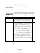
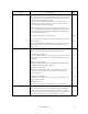
Task Installation Alert message Page Device Damage Be sure to turn on the power supply before inserting your cartridge for the first time. It releases the device from transport protection and enables you to insert the cartridge. The device may be damaged if you insert the cartridge without releasing the protection. From the next time, you don’t need to turn on the power supply beforehand. 3-18 Before moving the drive, remove the optical disk cartridge.
MANUAL ORGANIZATION MCE3130AP, MCE3064AP and MCF3064AP OPTICAL DISK DRIVE PRODUCT MANUAL (C156-E142) MCE3130AP, MCE3064AP and MCF3064AP OPTICAL DISK DRIVE MAINTENANCE MANUAL viii • • • • • • GENERAL DESCRIPTION SPECIFICATIONS INSTALLATION REQUIREMENTS HOST INTERFACE OPERATION AND CLEANING DIAGNOSIS AND MAINTENANCE • • • • • MAINTENANCE AND DIAGNOSIS FAULT ANALYSIS REMOVAL AND REPLACEMENT PROCEDURES PRINCIPLES OF OPERATION CLEANING C156-E142-02EN
REFERENCED STANDARDS Item Number Name Organization 1 X3T13/1321D Revision 2 AT Attachment with Packet Interface-5 (ATA/ATAPI-5) American National Standards Institute (ANSI) 2 SFF-8070I Revision 1.
CONTENTS page CHAPTER 1 GENERAL DESCRIPTION ................................................................................ 1 - 1 1.1 Features ................................................................................................................................. 1 - 1 1.1.1 Performance .......................................................................................................................... 1 - 2 1.1.2 Reliability.............................................................
3.1.3 Air flow................................................................................................................................. 3 - 3 3.1.4 Temperature rise under several conditions............................................................................ 3 - 4 3.1.5 Air purity............................................................................................................................... 3 - 4 3.2 Mounting Requirements .................................................
4.3.1.6 ATAPI Byte Count register................................................................................................... 4 - 7 4.3.1.7 ATAPI Block Device Select register .................................................................................... 4 - 8 4.3.1.8 Error register ......................................................................................................................... 4 - 8 4.3.1.9 ATA Features register ..........................................................
4.5.7 IDLE IMMEDIATE (X'95'/X'E1') ........................................................................................ 4 - 31 4.5.8 NOP (X'00')........................................................................................................................... 4 - 32 4.5.9 SERVICE (X'A2') (Not supported) ....................................................................................... 4 - 32 4.5.10 SET FEATURES (X'EF')..................................................................
4.6.24 WRITE AND VERIFY command ........................................................................................ 4 - 71 4.6.25 WRITE BUFFER command ................................................................................................. 4 - 72 4.6.26 WRITE LONG command ..................................................................................................... 4 - 74 4.7 Timing...................................................................................................
FIGURES page 1.1 Outer view (with panel)......................................................................................................... 1 - 6 1.2 Outer view (without panel).................................................................................................... 1 - 6 1.3 Optical disk drive configuration............................................................................................ 1 - 7 1.4 Control circuit section block diagram .......................................
5.3 Removing cartridge............................................................................................................... 5 - 5 5.4 Optial disk cartridge.............................................................................................................. 5 - 7 5.5 Write protect tab ................................................................................................................... 5 - 8 5.6 Cleaning procedure (1).....................................................
TABLES page 2.1 Model and order number....................................................................................................... 2 - 1 2.2 Specifications ........................................................................................................................ 2 - 3 2.3 Environmental and power requirements................................................................................ 2 - 7 2.4 Recommended optical disk cartridge specifications...............................
4.25 EXECUTE DEVICE DIAGNOSTIC command ................................................................... 4 - 29 4.26 Self-diagnosis detailed code.................................................................................................. 4 - 30 4.27 GET MEDIA STATUS command ........................................................................................ 4 - 30 4.28 Error register ..........................................................................................................
4.61 Changeable values in the caching page ................................................................................. 4 - 49 4.62 Default values for the cashing page....................................................................................... 4 - 49 4.63 Removable block access capabilities page ............................................................................ 4 - 50 4.64 Changeable values in the removable block access capabilities page.....................................
4.97 Sense key............................................................................................................................... 4 - 63 4.98 Logical block address format ................................................................................................ 4 - 64 4.99 ASC/ASCQ list (1/2)............................................................................................................. 4 - 64 4.100 Format Progress Indication Bytes ......................................
CHAPTER 1 GENERAL DESCRIPTION 1.1 Features 1.2 Drive Configuration 1.3 System Configuration This chapter describes the features and configuration of the optical disk drives. The MCE3130AP, MCE3064AP, MCF3064AP (hereafter optical disk drives) is disk that maintain the compatibility and intend high speed as the succeed drive of the MCE3130AP, MCE3064AP, MCF3064AP. The MCE3130AP, MCE3064AP, MCF3064AP is high-performance, 90mm(3.
1.1.1 Performance (1) Half-height standard 90mm(3.5-inch) size (25.4 mm height) The ATAPI controller can be directly connected to the system EIDE bus. The controller meets the specifications of the standard 25.4 mm height 90mm(3.5-inch) fixed disk drive form factor. (2) High-speed data transfer The speed of the MCE3130AP disk medium is 3,214 rpm when a 1.3 GB disk medium is used. When other media are used, the speed is 4,558 revolutions per minute.
(8) Automatic spindle stop function If access is not made within a certain time, this function stops disk rotation to minimize dust accumulation on the disk. This function can be set that time by the MODE SELECT command. 1.1.2 Reliability (1) Mean time between failure (MTBF) This drive features a 120,000 hour MTBF. (2) Error recovery For the error depending on the optical disk drive, recovery process is made by a suitable retry.
(2) Low noise and low vibration This drive operates quietly 26 dB or less (A character) even during seek operations and will not degrade the office environment. Rubber vibration isolators support the drive and minimize vibration. (Low noise and low vibration features are available except while an MO cartridge is being ejected.) (3) Vibration resistance (shock resistance) Rubber vibration isolators protect the drive against external shock or vibration. (4) Safety standards ! ! ! ! ! (5) UL1950 (U.S.A.
(3) Data buffer 1,844 KB buffer is used to transfer data between the EIDE bus and disk. Since data is stored in this buffer, the host can execute input-output processing effectively by using the high-speed data transfer capability of the EIDE bus without regard to the data transfer rate of the optical disk drive.
1.2 Drive Configuration 1.2.1 Drive model Figures 1.1 and 1.2 show the outer view. Figure 1.1 Figure 1.
1.2.2 Configuration Figure 1.3 shows the drive configuration. The drive consists of mechanical sections, a fixed optics section, actuator, and a control circuit section. The mechanical sections include the spindle motor, actuator section, bias magnet, and the cartridge folder vertical motion mechanism. The fixed optics section consists of the optical components, position detector, and LD controller. The control circuit sections include the drive control circuit section and ATAPI controller section.
(4) Separate optical sections The optical head section is separated in such a way that the fixed optics section is separated from the moving optics section to minimize seek time and positioning error. (See Subsection 1.2.4 for the fixed optical section.) This reduces the weight of the moving parts. The fixed optics section consists of the laser diodes, collimator lens, and optical detector.
The control circuit section is divided into two parts: an ATAPI controller section which deals with control between the ATAPI interface and drive interface, and a drive circuit section which controls the drive. (1) ATAPI controller circuit section The ATAPI controller circuit's reliability is improved by large-scale integrated circuit technology. The high-speed microprocessor (MPU) handles ATAPI interface control and drive control such as drive read-and-write control and single-beam control.
1.3 System Configuration Figures 1.5 and 1.6 show the PC AT interface system configuration. The interface can be directly connected to the 40-pin AT-compatible EIDE interface. HA (Host adapter) Host system EIDE interface AT bus (Host interface) Figure 1.5 ODD System configuration with one optical disk drive ODD HA (Host adapter) Host system AT bus (Host interface) ODD EIDE interface Figure 1.
CHAPTER 2 SPECIFICATIONS 2.1 Optical Disk Drive Specifications 2.2 Optical Disk Cartridge Specifications 2.3 Defect Management This chapter contains the specifications of the optical disk drive, and the optical disk cartridge. 2.1 Optical Disk Drive Specifications 2.1.1 Model and product number Table 2.1 lists the model and order number. Table 2.1 Model Name MCE3130AP MCE3064AP Order No.
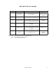
Table 2.1 Model and order number (2 of 2) Model Name Order No. Panel Panel Color Mounting Screws MCF3064AP CA05437-B501 CA05437-B531 with panel Light gray (2.5Y 7.2/0.4) Metric screws (M3) CA05437-B631 with panel Light gray (2.5Y 7.2/0.4) Inch screws (32 UNC) CA05437-B701 CA05437-B731 without panel ––– Metric screws (M3) CA05437-B831 without panel ––– Inch screws (32 UNC) Note: The panel colors (2.5Y 7.2/0.4) are indicated in Munsell symbols.
2.1.2 Drive specifications Table 2.2 lists MCE3130AP, MCE3064AP, MCF3064AP drives specifications Table 2.2 Specifications (1 of 4) [MCE3130AP] Item Specifications Optical disk cartridge Total capacity Capacity/track Capacity/sector 128 MB media 230 MB media 540 MB media 640 MB media 1.3 GB media Unformatted 181 MB 325 MB 819 MB 818 MB 1.683 GB Formatted 230 MB 538 MB 643 MB 1.
Table 2.
Table 2.
Table 2.2 Specifications (4 of 4) *1 The number of user tracks indicates the maximum user zone which includes the spare area and slipping area. *2 Mathematical average of 1,000 times of seek and does not include command overhead nor track address recognition time. Furthermore, it may reach a maximum of 35 ms depending on the quality of media and drive installation environment. *3 Loading time is the time from when the optical disk cartridge is inserted to when the optical disk drive is ready.
2.1.3 Environmental and power requirements Table 2.3 lists the environmental and power requirements. Table 2.3 Environmental and power requirements (1 of 2) Item Power requirements Power consumption Dimensions (W"D"H) Average +5 VDC±5%, 1.1 A (2.5 A Max.) (*1) Ripple requirement 100mV P-P (DC-1 MHz) MCE3130AP MCE3064AP, MCF3064AP Ready 3.9 W (typical) (*2) 3.9 W (typical) (*2) Random seek, read/ or write 5.5 W (typical) (*2) 5.
Table 2.3 Environmental and power requirements (2 of 2) Item Altitude Ambient for purity Specification Operating 3,000 m (10,000 ft) or less Idle 12,000 m (40,000 ft) or less Air flow Unused (*4) Air purity General office environment or better (dust perticles: Class 5 millions or less) Note: 1. Current limiter value for +5 VDC power: 5 A or less 2. Specifications under transporting condition are under the packaging specified by Fujitsu. 3.
2.1.5 Reliability (1) Mean time between failures (MTBF) The MTBF is 120,000 hours or more. Failure due to disk errors is not included. Conditions $ Power-on time: 200 hours/month or less $ LD-on time: 20% or less of power-on time $ Environment Temp.: 25°C Note: The MTBF is defined as follows: total operating time in all fields (hours) MTBF= number of device failure in all fields 1) Operating time is the total time power is applied.
2.2 Optical Disk Cartridge Specifications 2.2.1 Recommended optical disk cartridge specifications Specifications comply with the ISO/IEC 10090 standard for 128 MB disk, ISO/IEC 13963 standard for 230 MB disk, and ISO/IEC 15041 standard for 540 MB disk, and 640 MB disk. The following three disk types comply with the specifications. Table 2.4 shows the specifications of the optical disk cartridge recommended for this optical disk drive. The use of another disk cartridge may lower drive performance.
2.2.2 Optical disk cartridge Figure 2.1 shows an optical disk cartridge. The figure below shows the cartridge with its shutter open. $ Shutter closed 2) Shutter 1) Cartridge case 3) Write protect tab $ Shutter open 4) Disk 5) Hub Figure 2.
The following explains the components of the optical disk drive shown in Figure 2.1: 1) Cartridge case Covers the disk to protect it from damage when handled and facilitates disk replacement. The cartridge case is labeled and has a write protect tab. 2) Shutter Protects the disk against dust. When the cartridge is inserted into the optical disk drive, the shutter (metallic door) is opened. 3) Write protect tab The write protect tab selects whether write is enabled or disabled.
2.2.3 Disk specifications (1) 128 MB disk The ISO/IEC10090 defines 128 MB disk specification. (2) 230 MB disk The ISO/IEC13963 defines 230 MB disk specification. (3) 540 MB/640 MB disk The ISO/IEC15041 defines 540 MB/640 MB disk specification. (4) 1.3 GB disk The Cherry Book version 1.0 defines 1.3 GB disk specification. Table 2.5 lists disk specifications. Table 2.
2.3 Defect Management 2.3.1 Defect management schematic diagram Defective sectors on the disk shall be replaced by good sectors according to the defect management scheme as follows: Defective sectors found during surface certification are handled by a sector slipping algorithm. Defective sectors found after initialization are handled by a linear replacement algorithm. Figure 2.2 shows the algorithms for alternate processing. (a) Sector slipping algorithm (b) Linear replacement algorithm Figure 2.
Figure 2.
CHAPTER 3 INSTALLATION REQUIREMENTS 3.1 Environmental Requirements 3.2 Mounting Requirements 3.3 Power supply Requirements 3.4 Cable Connections 3.5 Jumper Settings 3.6 Notes on Drive Handling 3.7 Mounting 3.8 Cable Connections 3.9 Operation Confirmation and Preparation for Use after Installation 3.10 Dismounting Drive This chapter describes environmental, mounting, power supply, and connection requirements. 3.
(a) Inside optical disk cartridge Operating of inner partition wall Tip of thermocouple Hole for inserting thermocouple (b) IC (controller, read map) IC (controller) Figure 3.
3.1.2 Temperature requirements and measuring method Table 3.1 shows the temperature requirement at each measurement point shown in Figure 3.1. Table 3.1 Temperature requirements at measurement points Measurement point Maximum surface temperature Cartridge inside 55°C (*) IC (controller) surface 95 °C IC (read amp.) surface 85 °C Note: * 60°C for the optical disk cartridge (1.3 GB excluded) manufactured by Fujitsu. Following procedure is for temperature measurement of inside cartridge.
Note: Air flow temperature is 40°C and below. 3.1.4 Temperature rise under several conditions Table 3.2 Temperature at each measuring point (Reference) [Ambient atmospheric temperature of the optical disk drive: 45°C] Measurement point (°C) Ready Random seek Criteria Inside cartridge 49°C 54°C 55°C IC (controller) surface 50°C 70°C 95°C IC (read amp.) surface 48°C 70°C 85°C Thermal sensor 47°C 55°C — Notes: 3.1.5 1.
3.2 Mounting Requirements 3.2.1 External dimensions Figures 3.2 to 3.3 show the dimensions of the drive and the positions of the mounting holes. Unit: mm Note: The height length is 25.4 ± 0.8 besides the panel size. Figure 3.
Unit: mm Note: Those enclosed in parentheses are inch screws. Figure 3.
3.2.2 Installation direction Figure 3.4 shows the permissible installation directions for this drive. The mounting angle tolerance must be within –5" to 10" from the horizontal. (–) shows that the insertion faces below. # Horizontal # Vertical (Two orientations) Figure 3.
3.2.3 Centers of gravity Figure 3.5 shows the centers of gravity of the drive. Unit: mm Figure 3.
3.2.4 Notes on mounting (1) Mounting frame structure and clearance a) For vibration resistance and heat dissipation, this optical disk drive uses an embossed structure as shown in Figure 3.6, as well as a frame which has a construction similar to other frames which perform the same function. b) As shown in Figure 3.6, the inward projection of the mounting screw from the outer surface of the drive frame must not exceed 3 mm.
(2) Panel function processing When installed in a cabinet, do not change the panel formal. The processing is installation status and the disk insertion door can be closed from any locations. (3) Service clearance Figure 3.7 shows locations which must be accessed for installation and maintenance. Be sure to leave sufficient service clearance. P side # Cable connection R side # Mounting screw hole Q side # Mounting screw hole Figure 3.
(7) System ground The optical disk drive should be grounded to the signal ground (SG) of the power supply of the system. This SG line should be supplied with the system. The Frame Ground is shorted in the optical disk drive by a metal strip attached to the vibration isolation rubber between the frame (FG) and the base (SG).
3.4 Cable Connections 3.4.1 Drive connectors The optical disk drive (ODD) has connectors. Figure 3.9 shows the location of the connectors. # AT interface connector (40-pin) and power supply connector (4-pin) 1 pin 4 pin 2 pin CN1 Figure 3.
3.4.2 Cable connector specifications Table 3.3 lists the recommended cable connector specifications. Table 3.
3.5 Jumper Settings 3.5.1 Jumper settings at factory shipping Figure 3.11 shows jumper settings at factory shipping. 5 CNH1 CNH5 3 1 : Short 6 4 2 5-6 short-circuited: Sets the master device. Figure 3.11 Jumper settings at factory shipping 3.5.2 Mode setting (1) Setting master device mode Figure 3.12 shows the setting for recognizing the master device (device 0). 5 CNH1 CNH5 3 1 6 4 2 Figure 3.
(2) Setting slave device mode Figure 3.13 shows the setting for recognizing the slave device (device 1). 5 CNH5 CNH1 3 1 6 4 2 Figure 3.13 Slave device setting (3) Setting cable select mode Figure 1.14 shows the master device/slave device setting when the CSEL signal is connected to the interface. In the example shown in Figure 3.16, this setting requires a special interface connection. 5 6 CNH5 3 1 4 2 Figure 3.14 Cable select mode setting Figure 3.
CSEL conductor Open GND Host system Master device Slave device Example 1 CSEL conductor Open GND Host system Slave device Example 2 Figure 3.
3.6 Notes on Drive Handling (1) General notes Note the following points to maintain drive performance and reliability: Device damage 1) Shock or vibration applied to the drive that exceeds the values defined in the standard damage the drive. Use care when unpacking. 2) Do not leave the drive in dirty or contaminated environments.
(3) Installation a) Do not connect or disconnect the connectors or change the terminal settings when the power is on. b) Do not move the drive with the power on. c) Eject the optical disk cartridge, lock the carriage securing the head, turn off the power, then move the drive. Device damage Be sure to turn on the power supply before inserting your cartridge for the first time. It releases the device from transport protection and enables you to insert the cartridge.
Desiccant Desiccant Conductive bag Use a sealing tape MCE3130AP, MCE3064AP, MCF3064AP Eject Pin (% 20) Eject pin (Use a sealing tape) Support (Front, Rear) Support (Middle) Shipping Label (2) box Master carton (12/24 units) Figure 3.16 Individual packaging style (5) Figure 3.17 Gathered packaging style Transportation a) Transport the package with the UP sign upward. b) After unpacking, minimize the transportation distance and use cushions to avoid shock and vibration.
3.7 Mounting 3.7.1 Checks before mounting the drive Before mounting the optical disk drive in the system cabinet, check whether the jumper settings are set correctly. 3.7.2 Mounting procedure How the drive is mounted depends on the system cabinet structure. Determine the mounting procedure in consideration of the requirements of each system. This section contains the general mounting procedure and check items. See Section 3.2 for details on mounting drive.
3) Connect the AT interface cable. 4) After each cable connector is connected, secure the cable so that the cable does not touch the drive or the parts on the PCA or obstruct the flow of cooling air in the system cabinet. 3.9 Operation Confirmation and Preparation for Use after Installation 3.9.1 Confirming initial operations This section provides the operation check procedures after the power is turned on.
3.9.2 Connection check When initial operation check terminates normally after the power is turned on, check whether the drive is correctly connected by issuing command from the host system. Checking procedure depends on the host system configuration. If processing terminates abnormally: a) If sense data has been obtained by the REQUEST SENSE command, analyze the sense data. If the error is recoverable, retry the processing.
CHAPTER 4 HOST INTERFACE 4.1 Pin Assignment 4.2 Signal Description 4.3 Interface Registers 4.4 Various Processes 4.5 ATA Commands 4.6 Packet Commands 4.7 Timing The differences in host interface specifications between the MCE3130AP, MCE3064AP and MCF3064AP are shown in Table 4.1, Differences in Host Interface Specifications of Each Model.
4.1 Pin Assignment The table below lists pin assignments of the interface connector. Table 4.
Table 4.
4.2 Signal Description Table 4.3 PIN Signal name Signal description I/O Description 1 RESET- I 3, 5, 7, 9, 11, 13, 15, 17, 18, 16, 14, 12, 10, 8, 6, 4 DD7-0 DD15-8 I/O 21 DMARQ O Data request signal for DMA transfer 23 DIOW- I Write strobe signal. 25 DIOR- I Read strobe signal 27 IORDY O This is the ready signal for the host computer.
4.3 Interface Registers 4.3.1 I/O registers This section provides the I/O register functions and mapping. depending on which ATA or ATAPI commands are used. Table 4.
4.3.1.1 Alternate Status register This register contains the same information as that of the ATAPI Status register, except that the ODD does not recognize interrupts when reading this register. Therefore, the ODD does not clear the INTRQ signal and does not clear interrupts during the pending. Table 4.5 7 6 BSY DRDY 5 Bit definitions of Alternate Status register 4 Reserved SERVICE (0b) 3 2 1 0 DRQ CORR (0b) Reserved (0b) CHECK Read 4.3.1.
4.3.1.5 Drive Address register This register's bits are defined as shown below. Table 4.7 Bit definitions of Drive Address register 7 6 5 4 3 2 1 0 HiZ nWTG nHS3 nHS2 nHS1 nHS0 nDS1 nDS0 ! HiZ is always in the high-impedance state. ! nWTG indicates the status of the ODD internal data write control signal (Write Gate). ! nHS3 indicates a binary complement of bits 3 to 0 of the drive select register. ! nDS1 is the device select bit for device 1. It is 0 when device 1 is selected.
4.3.1.7 ATAPI Block Device Select register This register's bits are defined as shown below. Table 4.9 Bit definitions of ATAPI Block Device Select register 7 6 5 4 3 Unused Unused Unused Dev Unused 2 1 0 LUN R/W ! Bits 7, 6, 5, and 3 are not used. The ODD ignores all value sets in these bits. ! Dev indicates the device address. When Dev is 0, device 0 is selected and when Dev is 1, device 1 is selected. ! LUN (Logical Unit Number) is not supported.
4.3.1.9 ATA Features register This register is used for the SET FEATURES command. 4.3.1.10 ATAPI Features register This register's bits are defined as shown below. Table 4.11 Bit definitions of ATAPI Features register 7 6 5 4 3 2 Reserved ! All values in bits 7 to 2 are ignored. ! OVERLAP is ignored. ! When DMA is 1, the ODD performs DMA transfer for data. 1 0 OVERLAP DMA Write 4.3.1.11 ATA Sector Count register This register is used for the SET FEATURES command. 4.3.1.
Table 4.13 IO and Cod IO CoD Meaning 0 1 Packet command transfer 1 0 Data or parameter transfer (from the ODD to the host) 0 0 Data or parameter transfer (from the host to the ODD) 1 1 The completion status in the Status register is effective. 4.3.1.13 Sector Number register This register is not used. The ODD ignores all specified values. 4.3.1.14 ATAPI Status register This register indicates the status of the ODD.
b) Within 400 ns of receiving a command when the DRQ bit is not set c) Between data transfer blocks of the PIO data-in/PIO data-out command when the DRQ bit is not set d) After data block transfer with the PIO data-out command when the DRQ bit is not set e) During DMA transfer when the DRQ bit is not set In all other cases, the ODD does not set BSY.
4.4 Various Processes 4.4.1 Reset response There are four types of resets. ! Power-on reset ! ! Hardware reset ! ! The ODD performs initialization such as initial diagnostics and default setting. If any media is mounted, it also spins up media. The ODD is reset when the RESET- signal is asserted. The ODD initializes the interface controller by setting default values. ATA reset (Software reset) ! The ODD is reset when the SRST bit of the Device Control register is set.
4.4.2 Defect sector management Sector mapping is executed based on the ISO/IEC 10090 standard for 128 MB media, the ISO/IEC 13963 standard for 230 MB media, the ISO/IEC 15041 standard for 540 and 640 MB media, and the GIGAMO 90 mm Magneto-optical Disk System - System Description standard for 1.3 GB . Basically, possibly defective sector management is not required for the host. Defective sectors cannot be deleted from the host, except for certifying recordable areas.
4.4.4 Data error detection criteria Table 4.16 lists criteria used to detect ID errors and data errors for data access commands and error handling. Table 4.16 ID error and read error detection criteria and error handling Command ID read error Data error Error handling FORMAT UNIT 128 MB/230 MB media: 3 read errors in 3 sectors 540 MB/640 MB/1.3 GB media: 2 read errors in 2 sectors Error in 4 bytes or more per interleaving section Register error sectors in the PDL (Primary Defect List).
4.4.5 Cache function The ODD supports the read cache and MO write cache. The read cache consists of the read ahead cache and the LRU cache that reads write data remaining in the data buffer. The read ahead cache allows for data transfer at a near effective transfer speed during continuous read operation without causing any delay owing to rotation latency. LRU allows for data transfer with no mechanical operation if write and read operations are executed frequently on the same sector.
When the cache is enabled, the buffer contains data transferred from the host with a write command. If a read command is issued to the sector address at this time, the ODD directly transfers data to the high-level equipment from the data buffer without reading it from media. If the cache is hit with a read command, the ODD makes the data in the hit segment being kept in the highest priority. The data listed below cannot be stored in the read cache.
! Software reset Particularly under the condition described below, a command end response or data transfer to the host may be delayed until the write operation to media is completed. ! When a command that requires a new segment is received while all segments in the data buffer are used Under the conditions given below, write data in the buffer may not be written properly on media: ! ! ! 4.4.
4.4.7.1 Power mode The ODD supports power modes shown below. The ODD uses a power mode equivalent to standby mode, except that the DRDY bit is 0 while media is not mounted. ! ! ! ! ! Active mode Pre-idle mode Idle mode Standby mode Sleep mode 4.4.7.2 Active mode In active mode, all circuits are enabled. The ODD requires the shortest time to start processing a command. 4.4.7.3 Pre-idle mode In pre-idle mode, the read/write circuits stop.
4.4.7.6 Sleep mode Sleep mode uses power consumption as standby mode. To set the ODD in sleep mode, the host must issue the Sleep command. To restore the ODD from sleep mode, hardware reset or software reset is required. The host must not issue any command after the Sleep command. The ODD requires 15 seconds (standard) to respond. 4.4.7.7 Standby timer The standby timer is used to count the time during which the host issues no command. The standby timer value is programmable with the MODE SELECT command.
4.4.8 LED Indications The ODD notifies the operator of a serious error by turning on or blinking the LED lamp. Table 4.17 lists indication modes and operation. Table 4.
4.5 ATA Commands Table 4.18 lists supported ATA commands. This section represents ODD registers as shown below. Cylinders High/Low registers: CY Sector register: SC Device/Head register: DH Sector Number register: SN Features register: FR Table 4.
Note: 1. CY = Cylinder register SC = Sector register DH = Device/Head register SN = Sector Number register FR = Features register y - This register contains parameters effective to run the command. D - Indicates that only the Device parameter is effective and the LUN parameter is ineffective. D* - Device 0 is addressed, but both devices execute the command. 2. The protocol above indicates the command protocol used. ND - A non data command PI - A PIO data-in command 4.5.
Table 4.20 Device parameter information (1/5) Word Value 0 87c0h Bits Description General configuration information 15-14 13 12-8 7 Protocol type (B'10' = ATAPI device) Reserved Device type B'00111' = Optical disk unit Replaceable media device (B'1') 6-5 CMD DRQ type (B'10' = Accelerated DRQ) 4-2 Reserved 1-0 Command packet size (B'00' = 12 bytes) 1-9 0000h Reserved 10-19 "xxx...
Table 4.20 Device parameter information (2/5) Word Value Bits Description 51 0200h 15-8 PIO data transfer cycle timing mode 7-0 Reserved 52 0000h 15-0 Reserved 53 0003h 15-3 2 Reserved 88 word information is valid. (In the case of models which do not support Ultra-DMA transfers, B'0'.) 1 Information in words 64 to 70 is valid. (B'1') 0 Information in words 54 to 58 is valid.
Table 4.
Table 4.20 Device parameter information (4/5) Word Value 84 4000h Bits Command set supported 15 Always B'0'. 14 Always B'1'. 13-0 85 Description 4278h (Default value) Reserved Command set supported and whether the function is enabled or disabled (A value of less than 1 indicates that the command is supported and enabled.
Table 4.20 Device parameter information (5/5) 88 0000h 89126 0000h 127 0001h 15-0 Reserved. Reserved 15-9 8 Reserved Device write protected A value of 1 indicates device write protected. See 9.5.5 Timer & Protect Page 128255 4.5.2 7-2 Reserved 1-0 Media status notification function supported (B'01') 0000h Reserved PACKET (X'A0') Table 4.
4.5.3 DEVICE RESET (X'80') Table 4.22 DEVICE RESET command Bit 7 6 5 4 3 2 1 0 CM 0 0 0 0 1 0 0 0 DH X X X DRV X X X X CH X X X X X X X X CL X X X X X X X X SN X X X X X X X X SC X X X X X X X X FR X X X X X X X X The DEVICE RESET command resets the ODD. When the ODD receives the DEVICE RESET command, it sets the BUSY bit to 1. After reset is completed, the ODD sets the BUSY bit to 0. INTRQ is not asserted. 4.5.
Table 4.24 Power mode indication Power mode status 4.5.5 SC register Standby mode 00h Entering standby mode 00h Returning from standby mode 00h Idle mode FFh Active mode FFh EXECUTE DEVICE DIAGNOSTIC (X'90') Table 4.
abnormally and the ODD makes OR-operation to its self-diagnostics results of unit 0 (Device 0) with X'80' and sets it in the Error register. If device 1 ends abnormally, the ODD sets the CHECK bit of the Status register. When the ODD is device 1 The ODD asserts the PDIAG- signal within five seconds. It sets X'01' in the Error register and ends the command. Table 4.26 Self-diagnosis detailed code Detailed code 01h Normally end 02h-7Fh 8xh 4.5.
Otherwise, the command ends normally. If a hardware error by which the command cannot be executed occurs, as is the case with other commands, the command ends with Aborted Command. Table 4.28 Error register Bit7 Bit6 Bit5 Bit4 Bit3 Bit2 Bit1 Bit0 0 WRT_PT MC 0 MCR 0 NOMED 0 WRT_PT: Set to 1 when write-protected. MC: Set to 1 when media is exchanged. Reported only once. MCR: Set to 1 when the Eject switch is pressed. Reported only once. NOMED: Set to 1 when no media is inserted. 4.5.
4.5.8 NOP (X'00') Table 4.30 NOP command Bit 7 6 5 4 3 2 1 0 CM 0 0 0 0 0 0 0 0 DH X X X DRV X X X X CH X X X X X X X X CL X X X X X X X X SN X X X X X X X X SC X X X X X X X X FR X X X X X X X X The NOP command enables 16-bit access for Status register checking. The ODD judges an unsupported command. The command ends with Aborted Command. 4.5.9 SERVICE (X'A2') (Not supported) Table 4.
4.5.10 SET FEATURES (X'EF') Table 4.32 SET FEATURES command Bit 7 6 5 4 3 2 1 0 CM 1 1 1 0 1 1 1 1 DH X X X DRV X X X X CH X X X X X X X X CL X X X X X X X X SN X X X X X X X X SC Setting value FR Setting value The SET FEATURES command changes the ODD operating mode to the mode set in the SC and FR registers. If the specified value is not supported by the ODD or an invalid value, the ODD reports Aborted Command. Table 4.
Table 4.
Table 4.35 Cylinder High register Bit7 Bit6 Bit5 Bit4 Bit3 Bit2 Bit1 Bit0 0 0 0 0 0 POWER_EJ LOCK PRV_ENAB POWER_EJ: Set to 1. LOCK: Set to 1. PRV_ENAB: Set to 1 when the media status notification function is enabled. 4.5.11 SLEEP (X'99'/X'E6') Table 4.
4.5.12 STANDBY IMMEDIATE (X'94'/X'E0') Table 4.37 STANDBY IMMEDIATE command Bit 7 6 5 4 3 2 1 0 1 0 0 1 0 1 0 0 1 1 1 0 0 0 0 0 DH X X X DRV X X X X CH X X X X X X X X CL X X X X X X X X SN X X X X X X X X SC X X X X X X X X FR X X X X X X X X CM The ODD sets the power mode to standby mode.
4.6 Packet Commands The ODD supports the packet commands listed below. Table 4.38 Packet command codes and parameters Command Operation code Section ERASE (10) 2Ch 4.6.2 FORMAT UNIT 04h 4.6.3 INQUIRY 12h 4.6.4 MODE SELECT 55h 4.6.5 MODE SENSE 5Ah 4.6.6 PREVENT/ALLOW MEDIUM REMOVAL 1Eh 4.6.7 READ (10) 28h 4.6.8 READ (12) A8h 4.6.9 READ CAPACITY 25h 4.6.10 READ FORMAT CAPACITIES 23h 4.6.11 READ DEFECT DATA 37h 4.6.12 READ LONG 3Eh 4.6.
4.6.1 Logical Unit Number A value other than 0 is not supported for Logical Unit Number (LUN). It must always be 0. 4.6.2 ERASE command Table 4.39 ERASE command Bit Byte 7 6 0 5 4 3 2 1 0 Operation Code (2Ch) 1 Logical Unit Number Reserved 2-5 Logical Block Address 6 Reserved 7-8 Transfer Length 9-11 reserved The ERASE command erases data of the specified number of blocks from the specified logical block address.
4.6.3 FORMAT UNIT command Table 4.40 FORMAT UNIT command Bit Byte 7 6 5 4 0 3 2 1 0 Operation Code (04h) 1 Logical Unit Number FmtData CmpList 2 Reserved 3-4 Interleave 5-11 Reserved Defect List Format The FORMAT UNIT command formats media physically on the basis of the specified parameter values. When the FmtData bit is 1, the FORMAT UNIT parameter list must be transferred. When the FMtDAta bit is 1, the Defect List Format must be specified. Defect List Format can be 7 only.
When the DCRT (Disable Certification) bit is 1, the ODD formats media without checking it. When the IMMED (Immediate) bit is 1, the ODD responds with immediate end after the command is received and before formatting is completed. At this time, during formatting, the Ready bit of the Status register is set to 0, and then set to1 after formatting is completed. Defect List Length must be 8. If any other value is set, the command responds with Check Condition. Table 4.
Table 4.45 INQUIRY data Bit Byte 7 0 1 2 3 6 5 Reserved RMB (1b) 4 3 2 1 0 Peripheral Device Type Optical memory Device (07h) Reserved ISO Version (00b) ECMA Version (000b) Reserved ANSI Version (000b) Response data format (X'1') 4 Additional length (X'23') 5 Reserved 6 Reserved 7 Reserved 8-15 Vendor Information "FUJITSU" (in ASCII) Left justified. The rightmost data field not used is filled with space characters.
4.6.5 MODE SELECT command Table 4.46 MODE SELECT command Bit Byte 7 6 5 4 0 3 2 1 0 Operation Code (55h) 1 Logical Unit Number PF 2-6 Reserved 7-8 Parameter List Length 9-11 Reserved Reserved SP The MODE SELECT command sets various device operating modes. The PF (Page Format) bit must be 1. If the PF bit is 0, the command responds with Check Condition. When the SP (Save Pages) bit is 1, the ODD saves all parameter values transferred to the flash ROM.
Table 4.48 lists the mode parameter list. Table 4.48 Mode parameter list Bit Byte 7 6 5 4 3 0-7 Mode Parameter Header 0-n Page Descriptor(s) 2 1 0 The mode parameter list consists of a mode parameter header and page descriptor. Table 4.49 lists the mode parameter header. Table 4.49 Mode parameter header Bit Byte 7 6 5 4 3 0-1 Mode Data Length 2 Medium Type Code 3 WP 2 1 0 Reserved 4-7 Reserved Mode Data Length must be 0.
4.6.5.1 Drive operation mode page Table 4.51 Drive operation mode page Bit Byte 7 6 0 PS 0 5 4 3 2 1 0 Page Code (00h) 1 Page Length (02h) 2 SLM 3 SLR DVW Reserved Reserved DDE Reserved When the DVW (Disable Verify for WRITE) bit is 0, verification is made for the WRITE (10), WRITE (12), or WRITE AND VERIFY command. When the bit of DVW is 1, no verification is made. The SLM (Select LUN Mode) bit and the SLR (Select LUN for Rewritable) bit has no multiple LUNs and are always 0.
4.6.5.2 Read-Write error recovery page Table 4.54 Read-Write error recovery page Bit Byte 7 6 0 PS 0 5 4 3 2 1 0 Reserved DCR Page Code (01h) 1 Page Length (0Ah) 2 AWRE Reserved Reserved RC Reserved 3 Read Retry Count 4-7 Reserved 8 Write Retry Count 9-11 00h PER When the AWRE (Automatic Write Reallocation Enable) bit is 0, no automatic alternate block assignment is made for the WRITE (10), WRITE (12), or WRITE AND VERIFY command.
Read Retry Count must not be 3 or smaller. If a value of 3 or smaller is specified, the command assumes 4 and reports Recovered Error. Write Retry Count must not be a value other than 3. If a value other than 3 is specified, the command assumes 3 and reports Recovered Error. Write Retry operation is complicate and not always executed three times. To assure media compatibility, the read-write error recovery page should be set to the default value, except for diagnostics purposes.
4.6.5.3 Flexible disk page Table 4.57 Flexible disk page Bit Byte 7 6 0 0 0 5 4 3 2 1 0 Page Code (05h) 1 Page Length (1Eh) 2-3 Transfer Rate 4 Number of Heads 5 Sectors per Track 6-7 Data Bytes per Sectors 8-9 Number of Cylinders 10-19 Reserved 20 Motor off Delay 21-27 Reserved 28-29 Medium Rotation Rate 30-31 Reserved This page is supported for compatibility of device driver.
Table 4.58 Changeable values in flexible disk page Bit Byte 7 6 5 4 3 2-3 0000h 4 00h 5 00h 6-7 00h 8-9 0000h 10-19 0000h 20 00h 21-27 00h 28-29 0000h 30-31 00h 2 1 0 1 0 Table 4.59 Default values in flexible disk page Bit Byte 7 6 5 4 3 2 2-3 3E80h 4 40h 5 20h 6-7 In case of 640 Mbytes and 1.
4.6.5.4 Caching page Table 4.60 Caching page Bit Byte 7 6 0 PS 0 5 4 3 2 1 0 Reserved RCD Page Code (08h) 1 Page Length (0Ah) 2 Reserved WCE 3-11 Reserved When the WCE (Write Cache Enable) bit is 0, the write cache function for the WRITE (10), WRITE (12), or WRITE AND VERIFY command is disabled. When the bit of WCE is 1, the write cache function is enabled. When the RCD (Read Cache Disable) bit is 0, the read ahead cache function for the READ (10) or READ (12) command is enabled.
4.6.5.5 Removable block access capabilities page Table 4.63 Removable block access capabilities page Bit Byte 7 6 0 0 0 5 4 3 2 1 0 Page Code (1Bh) 1 Page Length (0Ah) 2 SFLP SRFP 3 NCD SML Reserved Reserved 4-11 TLUN Reserved The SFLP (System Floppy Type) bit indicates the system floppy disk device.
4.6.5.6 Timer & protect page Table 4.66 Timer & protect page Bit Byte 7 6 0 PS 0 5 4 3 2 Page Length (06h) 2 Reserved Reserved 4 Inactivity Time Multiplier Reserved 5-7 0 Page Code (1Ch) 1 3 1 DISP SWPP Reserved Inactivity Time Multiplier indicates the minimum time from the end of an access command until the ODD enters standby mode. Table 4.66 lists the relationship between the specified value and time.
When the DISP (Disable Media Access until Power cycle) bit is 1, the ODD responds with Not Ready for any command from the host until power-off or hardware reset. The ODD doesn't support DISP function. When the SWPP (Software Write Protect until Power-down) is 1, media is write-protected. The ODD doesn't support SWPP function. The DISP bit and SWPP bit can be saved. Table 4.
4.6.6 MODE SENSE command Table 4.70 MODE SENSE command Bit Byte 7 6 5 4 0 3 2 1 0 Operation Code (5Ah) 1 Logical Unit Number 2 Reserved PC Page Code 3-6 Reserved 7-8 Allocation Length 9-11 Reserved The MODE SENSE command transfers the mode parameter list to the host. The mode parameter list is shown in Table 4.71. PC (Page Control) specifies the type of the page descriptor to be sent. Table 4.
The mode parameter list consists of a mode parameter header and page descriptor(s). The mode parameter header is shown in Table 4.73. Table 4.
4.6.7 PREVENT/ALLOW MEDIUM REMOVAL command Table 4.75 PREVENT/ALLOW MEDIUM REMOVAL command Bit Byte 7 6 5 4 0 3 2 1 0 Operation Code (1Eh) 1 Logical Unit Number Reserved 2-3 Reserved 4 Reserved 5-11 Prevent Reserved The PREVENT/ALLOW MEDIUM REMOVAL command allows or inhibits media ejection on the device. A value of 0 in the Prevent bit allows ejection and a value of 1 disables ejection. The power-on default value is Enabled.
4.6.8 READ (10) command Table 4.77 READ command Bit Byte 7 6 5 0 4 3 2 1 0 Operation Code (28h) 1 Logical Unit Number Reserved 2-5 Logical Block Address 6 Reserved 7-8 Transfer Length 9-11 Reserved The READ (10) command reads data for the specified number of blocks from the specified logical block address and transfers it. Logical Block Address specifies the head logical block address used to start reading. Transfer Length specifies the number of blocks to be read and transferred.
When Transfer Length is 0, the command does not carry out data transfer. It simply ends normally without reading any data. It is recommended that the READ (10) command is used because there is ATAPI device which does not support the READ (12) command. 4.6.10 READ CAPACITY command Table 4.
Table 4.82 READ CAPACITY data (PMI = 1, PROM media) Bit Byte 7 6 5 4 3 2 0-3 Last Logical Block Address for MO area 4-7 Block Length in Bytes 4.6.11 1 0 1 0 READ FORMAT CAPACITIES command Table 4.83 READ FORMAT CAPACITIES command Bit Byte 7 6 5 0 4 3 2 Operation Code (23h) 1 Logical Unit Number Reserved 2-6 Reserved 7-8 Allocation Length 9-11 Reserved The READ FORMAT CAPACITIES command transfers data on the capacity of media currently loaded to the host.
Capacity List Length indicates the length of the capacity descriptor in bytes. Table 4.86 Current/Maximum capacity descriptor Bit Byte 7 6 5 4 0-3 3 2 1 0 Number of Blocks 4 Reserved 5-7 Descriptor Code Block Length Number of Blocks indicates the number of addressable blocks. Descriptor Code indicates the type of descriptor to be reported to the host. Block Length indicates the length of the block in bytes. Table 4.87 Descriptor code definition Descriptor Code 4.6.
The READ DEFECT DATA command transfers media defect data to the host. When Plist is 1, the command transfers header and PDL. When Glist is 1, this command transfers header and SDL. When both Plist and Glist are 0, it transfers the header. When both Plist and Glist are 1, the command transfers PDL and SDL. PDL and SDL are arranged in an ascending order. The defect list format supported is listed in Table 4.89. If any other format is specified, the command assumes the format listed in Table 4.
4.6.13 READ LONG command Table 4.92 READ LONG command Bit Byte 7 6 5 0 4 3 2 1 0 Operation Code (3Eh) 1 Logical Unit Number Reserved 2-5 Logical Block Address 6 Reserved 7-8 Byte Transfer Length 9-11 Reserved The READ LONG command reads data in the data, CRC, and ECC sections from the specified logical block address. The transfer byte length must be a multiple of 600 (X'258') bytes for 512 byte media and a multiple of 2380 (X'94C') bytes for 2048 byte media. 4.6.
4.6.15 REQUEST SENSE command Table 4.94 REQUEST SENSE command Bit Byte 7 6 5 0 4 3 2 1 0 Operation Code (03h) 1 Logical Unit Number Reserved 2-3 Reserved 4 Allocation Length 5-11 Reserved The REQUEST SENSE command transfers sense data to the host. Sense data indicates detailed error information on the command whose error was reported previously. If no error command was reported, SENSE KEY indicates NO SENSE.
When the Valid bit is 1, the information field (bytes 3 to 6) is effective. Error Code indicates the sense data format and type. See Table 4.96. Table 4.96 Error code Error Code Report timing X'70' (Current error) Reported for a normal error. X'71' (Deferred error) Reported when an error occurs in the command that accesses the write cache when the write cache is enabled. If this sense data is reported, the command that reported the Check Condition status is not executed. Sense Key outlines the error.
The information indicates LBA of an error block. If an error occurs in multiple blocks, the LBA of the first block is indicated. Command-Specific Information indicates the logical track address of the block indicated in Information (or logical block address). The track address format is shown in Table 4.98. Table 4.
Table 4.
The Sense-Key Specific field format is shown in Table 4.100. Format Progress Indication Bytes is effective only when Sense key is NOT READY and the SKSV bit is 1. Otherwise, the field is set with X'00'. This field is defined for the FORMAT UNIT command having the Immed bit of 1. Table 4.100 Format Progress Indication Bytes Bit Byte 7 15 SKSV 6 5 4 3 2 1 0 Reserved 16-17 Progress Indication Progress Indication indicates the formatting completion rate when the denominator is 655356 (X'10000').
4.6.17 SEEK command Table 4.102 SEEK command Bit Byte 7 6 5 0 4 3 2 1 0 Operation Code (2Bh) 1 Logical Unit Number Reserved 2-5 Logical Block Address 6-11 Reserved The SEEK command positions the head on the track at the specified logical block address. Logical Block Address specifies the logical block address at which the head is positioned. 4.6.18 START/STOP UNIT command Table 4.
Table 4.104 START/STOP/EJECT processing 4.6.19 LoEj Start Processing 0 0 Stops disk rotation. 0 1 Starts disk rotation and checks the format type of media. 1 0 Ejects media if possible. 1 1 Ends abnormally (ILLEGAL REQUEST). SYNCHRONIZE CACHE command Table 4.
4.6.20 TEST UNIT READY command Table 4.106 TEST UNIT READY command Bit Byte 7 6 5 0 4 3 2 1 0 Operation Code (00h) 1 Logical Unit Number Reserved 2-11 Reserved The TEST UNIT READY command checks if the device is ready for test and reports the device status to the host. If the ODD can end normally for appropriate access commands, the command responds with the Good status. Otherwise, the command responds with Check Condition to the host. 4.6.21 VERIFY command Table 4.
4.6.22 WRITE (10) command Table 4.108 WRITE (10) command Bit Byte 7 6 5 0 4 3 2 1 0 Operation Code (2Ah) 1 Logical Unit Number Reserved 2-5 Logical Block Address 6 Reserved 7-8 Transfer Lenght 9-11 Reserved The WRITE (10) command receives and writes data for the specified number of blocks from the specified logical block address. Logical Block Address specifies the head logical block address used to start writing.
Transfer Length specifies the number of blocks to be transferred and written. When Transfer Length is 0, the command does not carry out data transfer. It simply ends normally without writing any data. It is recommended that the WRITE (10) command is used because there is ATAPI device which does not support the WRITE (12) command. 4.6.24 WRITE AND VERIFY command Table 4.
4.6.25 WRITE BUFFER command Table 4.111 WRITE BUFFER command Bit Byte 7 6 5 4 0 3 2 1 0 Operation Code (3Bh) 1 Logical Unit Number Reserved 2 Reserved Reserved TNFY Reserved 3-5 Buffer Offset 6-8 Allocation Length 9-11 Reserved Mode Code-ID The WRITE BUFFER command downloads the firmware to the flash ROM. Mode must be set to 5. Otherwise, the command responds with Check Condition.
Table 4.112 Code-ID Code-ID Microcode type Download file size 0h Main Code 78040h 1h-Fh Reserved - Download procedure Example 1 - To transfer the download file of X'78040' bytes in size in one operation Step 1: Set X'78040' in Allocation Length, X'0' in Buffer Offset, 5 in Mode, and 0 in the TNFY bit and issue the command to transfer download file of X'78040' bytes to the device. Make sure that the command ends normally.
4.6.26 WRITE LONG command Table 4.113 WRITE LONG command Bit Byte 7 6 0 5 4 3 2 1 0 Operation Code (3Fh) 1 Logical Unit Number Reserved 2-5 Logial Block Address 6 Reserved 7-8 Byte Transfer Length 9-11 Reserved The WRITE LONG command writes data in the data, CRC, and ECC sections to the specified logical block address. The transfer byte length must be a multiple of 600 (X'258') bytes for 512 byte media and a multiple of 2380 (X'94C') bytes for 2048 byte media.
4.7 Timing 4.7.1 Register/PIO data transfer timing t0 DA(2:0) CS0-/CS1t1 t9 t2 t2i DIOR-/DIOW- WRITE DD(15:0) t3 t4 READ DD(15:0) t5 t7 t6 t6Z IOCS16- tA TRd IORDY tB Figure 4.
Table 4.
4.7.2 Multiword DMA data transfer timing CS0-/CS1tM tN t0 DMARQ tL DMACKtI tD tK tJ DIOR/DIOWtE READ DD(15:0) WRITE DD(15:0) tZ tG tF tH tG Figure 4.
Table 4.
4.7.3 Power-on and Reset Timing t10 RESET- Device 0 BSY t11 Device 0 DRDY Device 0 PDIAG-out Device 0 DASP-out t12 t13 Device 0 DASP-in Device 0 PDIAG-in t14 t15 Device 1 BSY Device 1 DRDY t16 Device 1 DASP-out t17 t18 Device 1 PDIAG-out *1 *2 *3 Device 0 sets the BSY bit to 0 when device 1 is not connected. Device 0 uses DASP- to indicate that it is in operation when device 1 is not connected. DASP- is used to indicate that the device is in operation. Figure 4.
Table 4.
CHAPTER 5 OPERATION AND CLEANING 5.1 Operating Optical Disk Drive 5.2 Cleaning Drive 5.3 Optical Disk Cartridge Operation 5.4 Cleaning Optical Disk Cartridge This chapter describes how to operate and clean the drive and the optical disk cartridges. 5.1 Operating Optical Disk Drive The drive has an automatic load function. All the operator must do is to insert the optical disk cartridge and operate the eject button.
1) Disk insertion slot Use this slot to insert and eject the optical disk cartridge. 2) Eject button & BUSY LED (display lamp) On this optical disk drive, this is the push button combining the eject button with the BUSY LED (display lamp) for ejecting the optical disk cartridge (it lights in green during seeking and during erasing, writing or reading of data). When ejection is disabled by the SCSI command, the optical disk cartridge cannot be taken out.
Notes (2) 1) The cartridge must be completely inserted until the BUSY LED indicator lamp is lit. 2) If the cartridge is inserted by pushing either left or right side of the cartridge rear, it may not be inserted completely. Be sure to push the central part straight into the drive until it is completely inserted. 3) If the BUSY LED indicator lamp does not light when the cartridge is inserted, once eject the cartridge by pressing the eject/BUSY LED button and insert it again.
Inserting direction Shutter Push by hand the width of 20mm to the right and left from the cartridge rear center, to the position shown at right. Figure 5.2 5.1.4 Inserting cartridge Ejecting (removing) cartridge Remove the cartridge as explained below. (1) When the drive power is on: 1) The cartridge can be removed by pressing the eject button. Notes: 1. If the command prevents ejection, the cartridge cannot be removed. 2. Remove the cartridge when completely ejected.
3) The optical disk drive unit should not be carried around with a cartridge loaded inside. Push the eject button Figure 5.
5.2 Cleaning Drive When a dust or smoke of cigarette is stained to the lens actuator, a performance of whole drive may be down. Clean the lens actuator periodically using following head cleaner. Note: Cleaning period differs depending on the installation condition. Usually, cleaning period is once a three months. Table 5.1 (1) Head cleaner Part name Order number Head cleaner CA90002-C980 Cleaning method Clean the head actuator with following method. 1. Turn on the power of the drive. 2.
5.3 Optical Disk Cartridge Operation 5.3.1 Optical disk cartridge Figure 5.4 shows the optical disk cartridge. For operation and cleaning, users should be familiar with the parts shown in the figure. See Subsection 2.3.2 for the functions of the parts. ! Shutter closed 2. Shutter 1. Cartridge case 3. Write protect tab ! Shutter open 4. Disk 5. Hub Figure 5.
5.3.2 Write protect tab Moving the write protect table determines whether to enable or disable writing of the optical disk cartridge. Use a fingernail to move the write protect tab (it must be completely moved to the end because there is play in the middle). Figure 5.5 shows the write protect tab location on the optical disk cartridge and the moving state of the write protect tab (see "write enabled" and write disabled" entered on the label).
5.3.3 Notes To maintain the performance and reliability of the optical disk cartridge, keep the following points in mind when using, storing, or transporting the cartridge: (1) When using the cartridge: ! ! ! ! (2) When storing the cartridge: ! ! ! (3) Do not place a heavy objects on the cartridge. Do not store the cartridge where exposed to direct sunlight or where the temperature changes sharply, the temperature is high, or the humidity is high. Do not store the cartridge in a dusty or smoky place.
Table 5.3 shows the packaged items in the cleaning kit. Table 5.3 Packaged items (cleaning kit) Name Contents Setting case 1 piece Cleaning cloth 5 pieces (70mm"#70mm) Cleaning solution 1 bottle (20ml) The following sub-kit is available as a set of the cleaning solution and cleaning cloth as supplement. ! Order No. CA90002-D901 Damage for disk medium Use the cleaning solution and cleaning cloth specified in Table 5.2. If other than the specified items is used, disk media surface may be damaged.
Damage for disk medium Clean the cartridge at clean place. Put a disposable groves at cleaning so that the fingerprint does not put on the disk media (recommendation). 1) Slide the shutter completely open. Figure 5.6 Cleaning procedure (1) 2) Set the cartridge with keeping label side down and shutter open to the shutter stopper of the setting case as shown in Figure 5.7. Cartridge Shutter Spindle Disk media Shutter stopped Setting case as shown Figure 5.
Damage for disk medium At setting the cartridge to the setting case, do not apply the heavy shock and push hardly. 3) Cover the cartridge with the setting case cover, then insert the spindle pin into the center hub of the cartridge. Disk media Revolver Cartridge opening Setting case cover Disk hub Figure 5.8 Cleaning procedure (3) 4) Remove a slender piece that causes a defect from the disk surface at wiping the disk media. 5) Moisten the cleaning cloth with a few drops of cleaning solution.
7) Turn the revolving knob, then wipe the disk surface. Cleaning cloth Figure 5.9 Cleaning procedure (4) 8) If the excess cleaning solution remains on the disk surface, wipe out with the cleaning cloth.
CHAPTER 6 DIAGNOSIS AND MAINTENANCE 6.1 Diagnosis 6.2 Maintenance Information This chapter contains diagnosis and maintenance information. 6.1 Diagnosis Table 6.1 shows a test executed by the diagnostic function. The drive has a self-diagnostic function. This function can check the basic operations of the drive. A test program running in the host system is required to check general operations, including operations of the interface with the host system. (See Subsection 6.1.3.) Table 6.
6.1.1 Initial self-diagnosis When the power is turned on, the optical disk drive starts initial self-diagnosis. Basic hardware functions are tested during initial self-diagnosis. The hardware function test checks the normality of the basic controller operation. This test includes the normality check of the ROM in which microcodes are stored, microprocessor (MPU) peripheral circuit test, memory (RAM) test, and data buffer test.
6.2 Maintenance Information 6.2.1 Maintenance requirements (1) Preventive maintenance No preventive maintenance is required. (2) Service life No overhaul is required within the first five years if the drive is used and handled in an appropriate environment. (3) Service system and repair Fujitsu provides a service system and repair facility for its optical disk drive. Submit information required to replace or repair the drive to your Fujitsu representative.
6.2.2 Revision number The revision number of an optical disk drive is represented with an alphabetic character and a single-digit number. The revision number is shown on the revision label attached to the drive. For example, Figure 6.1 shows the MCE3130SS revision label format. Revision number Figure 6.1 (1) Revision label Revision number indication When the drive is shipped, the revision number is indicated by deleting the numbers up to the corresponding number on the line of alphabetic characters.
Glossary Axial acceleration Acceleration on the recording layer along with the line perpendicular to the disk reference surface to a specified rotation speed. Axial acceleration is detected by optical means. Axial displacement A displacement at a point on the recording layer in a direction perpendicular to the disk reference surface from its original standard position.
Sense key A 4-bit code set in sense data. This information is used to classify the type of error detected. Spindle A component of the disk drive unit that is in contact with the disk and hub. GL - 2 Status A single-byte information reported from the target to the initiator at the end of each command execution. The status indicates the end status of a command.
Abbreviations A E AC ACK ALPG AM ANSI ARRE ASC ASCII ASCQ ATN AWG AWRE Alternating Current ACKnowledge Automatic Laser Power Control Address Mark American National Standards Institute Automatic Read Reallocation Enabled Additional Sense Code American Standard Code for Information Interchange Additional Sense Code Qualifier ATteNtion American Wire Gauge Automatic Write Reallocation Enabled B BCV BPV BSY BytChk Buffer Control Valid Bit Pointer Varid BuSY Byte Check CRC CSA DB DBD DBP DC DCRT DDS DMA DPO
N N.C.
Index Control circuit section 1 - 8, 1 - 9 Control circuit section block diagram 1 - 8 Controls the focus-tracking 1 - 9 CSA C22.2 No. 950 1 - 4 Current 3 - 11 Current waveform 3 - 11 25.
F Features 1 - 1 Fixed optics section 1 - 7 Mounting Requirements 3 - 5 Movable optics section 1 - 8 MPU 1 - 9 MTBF 1 - 3, 2 - 8 G General notes 3 - 17 H Head actuator 1 - 8, 1 - 9 Head cleaner 5 - 6 High-speed data transfer 1 - 2 High-speed mean seek time 1 - 2 Hub 2 - 15 I If processing terminates abnormally 3 - 22 Initial self-diagnosis 6 - 2 Input voltage 3 - 11 Inserting cartridge 5 - 2 Installation 3 - 18 Installation direction 3 - 7 Installation Requirements 3 - 1 Interface 1 - 4 ISO standard 1 - 2
Revision number 6 - 4 Revision number indication 6 - 4 Rubber vibration isolators 1 - 4 U S Safety standards 1 - 4 SCSI connection check 3 - 22 Sector slipping algorithm 2 - 13 Seek time 2 - 2 Seeks 1 - 7 Separate optical sections 1 - 8 Service clearance 3 - 10 Service system 6 - 3 Setting case 5 - 10 Setting case cover 5 - 12 Setting the cartridge 5 - 12 Shelf life 2 - 12 Shock resistance 1 - 4 Shutter 2 - 10, 2 - 11 Slipping 1 - 5 Specifications 2 - 1 Storage 3 - 19 Surface temperature measurement point
Comments concerning this manual can be directed to one of the following addresses: FUJITSU LIMITED Business Planning Solid Square East Tower 580 Horikawa-cho,Saiwai-ku, Kawasaki, 210-0913, Japan TEL: 81-44-540-4056 FAX: 81-44-540-4123 FUJITSU COMPUTER PRODUCTS OF AMERICA, INC. 2904 Orchard Parkway, San Jose, California 95134-2009, U.S.A. TEL: 1-408-432-6333 FAX: 1-408-432-3908 FUJITSU CANADA INC. 2800 Matheson Blvd.
FUJITSU LIMITED Reader Comment Form We would appreciate your comments and suggestions for improving this publication. Publication No. Rev. Letter Title How did you use this publication? Learning Installing Reference Maintaining What is your overall rating of this publication? Very Good Fair Good Current Date Is the material presented effectively? Sales Fully covered Operating Well Illustrated What is your occupation? Very Poor Poor Your other comments may be entered here.