
User's Manual
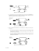
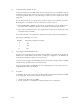


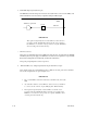

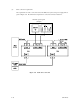
Table Of Contents
- Front Cover
- FOR SAFE OPERATION
- REVISION RECORD
- PREFACE
- Important Alert Items
- CONTENTS
- CHAPTER 1 GENERAL DESCRIPTION
- CHAPTER 2 SPECIFICATIONS
- CHAPTER 3 DATA FORMAT
- CHAPTER 4 INSTALLATION REQUIREMENTS
- CHAPTER 5 INSTALLATION
- CHAPTER 6 DIAGNOSTICS AND MAI TENANCE
- CHAPTER 7 ERROR ANALYSIS
- APPENDIX A SETTING TERMINALS
- APPENDIX B CONNECTOR SIGNAL ALLOCATION
- INDEX
- Addresses
- Reader Comment Form
- Back Cover
C141-E166 4-15
(5) External operator panel connector Signals
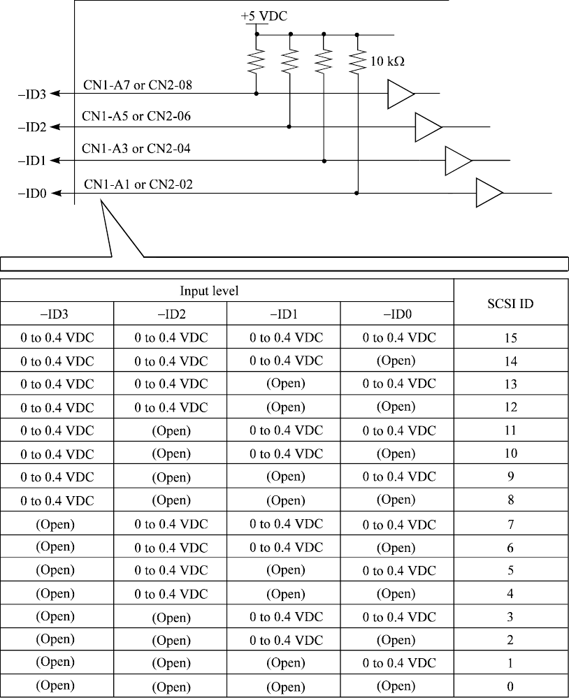
a. 16-bit SCSI –ID3, –ID2, –ID1, –ID0: Input signals (CN1-A1, A3, A5, A7 pin and CN2-02,
04, 06, 08 pin)
These signals are used for providing switches to set the SCSI ID of the IDD externally. Figure
4.18 shows the electrical requirements. For the recommended circuit examples, see Subsection
4.3.4.
Figure 4.18 16-bit SCSI ID external input