
User's Manual
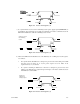
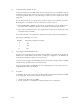


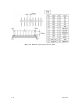

Table Of Contents
- Front Cover
- FOR SAFE OPERATION
- REVISION RECORD
- PREFACE
- Important Alert Items
- CONTENTS
- CHAPTER 1 GENERAL DESCRIPTION
- CHAPTER 2 SPECIFICATIONS
- CHAPTER 3 DATA FORMAT
- CHAPTER 4 INSTALLATION REQUIREMENTS
- CHAPTER 5 INSTALLATION
- CHAPTER 6 DIAGNOSTICS AND MAI TENANCE
- CHAPTER 7 ERROR ANALYSIS
- APPENDIX A SETTING TERMINALS
- APPENDIX B CONNECTOR SIGNAL ALLOCATION
- INDEX
- Addresses
- Reader Comment Form
- Back Cover
4-12 C141-E166
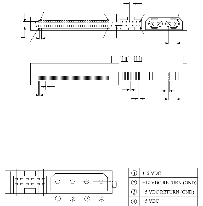
(2) SCSI connector and power supply connector
a. 16-bit SCSI
The connector for the SCSI bus is an unshielded P connector conforming to SCSI-3 type which
has two 34-pin rows spaced 1.27 mm (0.05 inch) apart. Figure 4.14 shows the SCSI
connector. See Section B.1 in Appendix B for the signal assignments on the SCSI connector.
For details on the physical/electrical requirements of the interface signals, refer to Sections 1.3
and 1.4 in the SCSI Physical Interface Specifications.
Pin 1
Pin 34
Pin 68
Pin 35
2.00m
Pin A1
Pin A2
Pin 1
2.54mm
5.08mm
1.30mm
2.00mm
5.08mm
1.27mm
0.40mm
0.635mm
0.40mm
1.00mm
Figure 4.14 16-bit SCSI interface connector
b. Power supply connector
Figure 4.15 shows the shape and the terminal arrangement of the output connector of DC
power supply.
Figure 4.15 Power supply connector (16-bit SCSI model)