
User's Manual

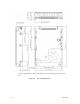

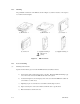
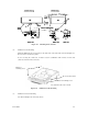


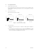
Table Of Contents
- Front Cover
- FOR SAFE OPERATION
- REVISION RECORD
- PREFACE
- Important Alert Items
- CONTENTS
- CHAPTER 1 GENERAL DESCRIPTION
- CHAPTER 2 SPECIFICATIONS
- CHAPTER 3 DATA FORMAT
- CHAPTER 4 INSTALLATION REQUIREMENTS
- CHAPTER 5 INSTALLATION
- CHAPTER 6 DIAGNOSTICS AND MAI TENANCE
- CHAPTER 7 ERROR ANALYSIS
- APPENDIX A SETTING TERMINALS
- APPENDIX B CONNECTOR SIGNAL ALLOCATION
- INDEX
- Addresses
- Reader Comment Form
- Back Cover
C141-E166 4-5
Figure 4.4 Mounting frame structure
(2) Limitation of side-mounting
Mount the IDD using the 4 screw holes at the both ends on the both sides as shown in Figure 4.5.
Do not use the center hole by itself.
In case of using the center hole, it must be used in combination with 2 holes on both ends.
(Total 6 screws for 6 holes enclosed)
Figure 4.5 Limitation of side-mounting
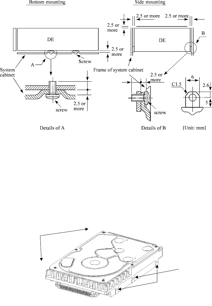
(3) Limitation of bottom-mounting
Use all 4 mounting holes on the bottom face.
4
3
2
1
Use four holes (No.1-4) to mount.
Holes for
mounting screw.
Holes for mounting screw.
Do not use these holes
5.0 or less
5.0 or less