
User's Manual
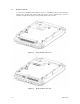
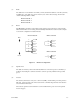
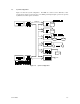
Table Of Contents
- Front Cover
- FOR SAFE OPERATION
- REVISION RECORD
- PREFACE
- Important Alert Items
- CONTENTS
- CHAPTER 1 GENERAL DESCRIPTION
- CHAPTER 2 SPECIFICATIONS
- CHAPTER 3 DATA FORMAT
- CHAPTER 4 INSTALLATION REQUIREMENTS
- CHAPTER 5 INSTALLATION
- CHAPTER 6 DIAGNOSTICS AND MAI TENANCE
- CHAPTER 7 ERROR ANALYSIS
- APPENDIX A SETTING TERMINALS
- APPENDIX B CONNECTOR SIGNAL ALLOCATION
- INDEX
- Addresses
- Reader Comment Form
- Back Cover
1-6 C141-E166
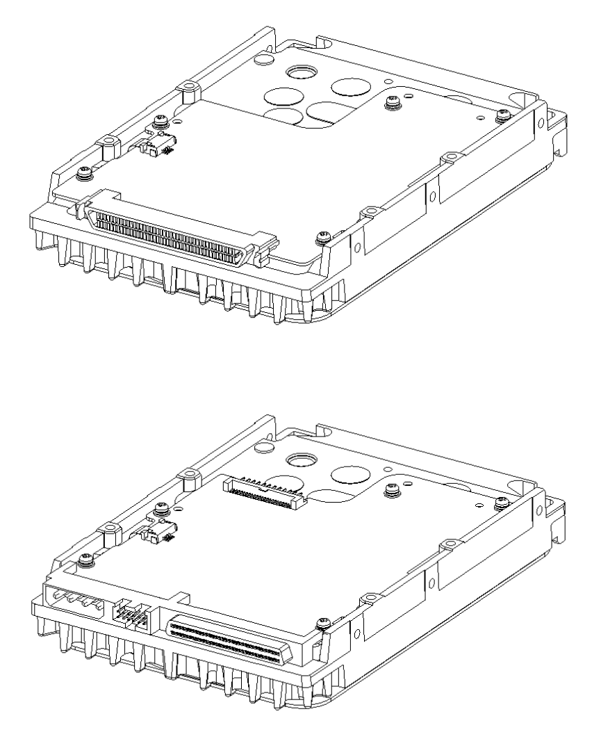
1.2 Hardware Structure
An outer view of the IDD is given in Figures 1.1 and 1.2. The IDD is composed of the disk, head,
spindle motor, mounted disk enclosure (DE) with actuator and air circulation filter, as well as
read/write pre-amp with the printed circuit assembly (PCA) of the controller.
Figure 1.1 NC model drives outer view
Figure 1.2 NP model drives outer view