C141-E166-01EN MAP3147NC/NP MAP3735NC/NP MAP3367NC/NP DISK DRIVES PRODUCT/MAINTENANCE MANUAL
FOR SAFE OPERATION Handling of This manual This manual contains important information for using this product. Read thoroughly before using the product. Use this product only after thoroughly reading and understanding especially the section “Important Alert Items” in this manual. Keep this manual handy, and keep it carefully. FUJITSU makes every effort to prevent users and bystanders from being injured or from suffering damage to their property. Use the product according to this manual.
REVISION RECORD Edition Date published 01 May, 2002 Revised contents Specification No.
Related Standards Product specifications and functions described in this manual comply with the following ANSI (*1) standards. Document number T10/1236D Rev.20 Title SCSI Primary Commands-2 (SPC-2) [NCITS.351:2001] T10/996D Rev.8c SCSI-3 Block Commands (SBC) [NCITS.306:1998] T10/1157D Rev.20 SCSI Architecture Model-2 (SAM-2) T10/1365D Rev.
PREFACE This manual describes the MAP3147NC/NP, MAP3735NC/NP and MAP3367NC/NP (hereafter, MAP series), 3.5 type fixed disk drives with an embedded SCSI controller. This manual details the specifications and functions of the above disk drive, and gives the requirements and procedures for installing it into a host computer system. This manual is written for users who have a basic understanding of fixed disk drives and their use in computer systems.
CONVENTIONS FOR ALERT MESSAGES This manual uses the following conventions for alerts to prevent physical or property damages to users or by standards. DANGER This indicates that personal injury will occur if the user does not perform the procedure correctly. WARNING This indicates that personal injury could occur if the user does not perform the procedure correctly. CAUTION This indicates that either minor or moderate personal injury may occur if the user does not perform the procedure correctly.
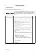
Important Alert Items Important Alert Messages The important alert messages in this manual are as follows: A hazardous situation could result in minor or moderate personal injury if the user does not perform the procedure correctly. This alert signal also indicates that damages to the product or other property may occur if the user does not perform the procedure correctly. Task Mounting Installation Alert message Data loss For MAP series, Reed Solomon codes are applied for their ECC.
Task Mounting Installation Alert message Page Damage 1. Be careful of the insertion orientation of the SCSI connectors. With the system in which terminating resistor power is supplied via the SCSI cable, if the power is turned on, the overcurrent protection fuse of the terminating resistor power supplier may be blown or the cable may be burnt if overcurrent protection is not provided. When the recommended parts listed in Table 4.2 are used, inserting the cables in the wrong direction can be prevented.
MANUAL ORGANIZATION PRODUCT/ MAINTENANCE MANUAL (This manual) 1. 2. 3. 4. 5. 6. 7. General Description Specifications Data Format Installation Requirements Installation Diagnostics and Maintenance Error Analysis SCSI Physical Interface Specifications 1. SCSI Bus 2. SCSI Message 3. SCSI Bus Error Recovery Processing SCSI Logical Interface Specifications 1. 2. 3. 4. 5.
This page is intentionally left blank.
CONTENTS page CHAPTER 1 GENERAL DESCRIPTION ............................................................................1-1 1.1 Standard Features ..............................................................................................................1-2 1.2 Hardware Structure............................................................................................................1-6 1.3 System Configuration ......................................................................................
4.3.2 SCA2 type SCSI model (NC model) .................................................................................4-19 4.3.3 Cable connector requirements ...........................................................................................4-20 4.3.4 External operator panel (on NP model drives only) ..........................................................4-22 CHAPTER 5 INSTALLATION...............................................................................................5-1 5.
6.3.3 Diagnostic test ...................................................................................................................6-12 6.4 Troubleshooting Procedures..............................................................................................6-13 6.4.1 Outline of troubleshooting procedures ..............................................................................6-13 6.4.2 Troubleshooting with disk drive replacement in the field ............................................
This page is intentionally left blank.
FIGURES Figure 1.1 page NC model drives outer view .................................................................................................1-6 Figure 1.2 NP model drives outer view .................................................................................................1-6 Figure 1.3 Disk/head configuration........................................................................................................1-7 Figure 1.4 System configuration .......................................
Figure 4.20 SCSI cables connection ......................................................................................................4-18 Figure 4.21 NC connectors location ......................................................................................................4-19 Figure 4.22 SCA2 type SCSI connector ................................................................................................4-20 Figure 4.23 External operator panel circuit example ...............................
TABLES Table 2.1 page Model names and order numbers..............................................................................................2-1 Table 2.2 Function specifications .............................................................................................................2-2 Table 2.3 Environmental/power requirements..........................................................................................2-4 Table 2.4 SCSI function specifications..................................
This page is intentionally left blank.
CHAPTER 1 GENERAL DESCRIPTION 1.1 Standard Features 1.2 Hardware Structure 1.3 System Configuration This chapter describes the feature and configuration of the MAP series intelligent disk drives (IDD). IDDs are high performance large capacity 3.5 type fixed disk drives with an embedded SCSI controller. The MAP series disk drives support the Small Computer System Interface (SCSI) as described in the ANSI SCSI SPI-4 [T10/1365D Rev.7] to the extent described in this manual.
1.1 Standard Features (1) Compactness Since the SCSI controller circuit is embedded in the standard 3.5 type fixed disk drive form factor, the IDD is extremely compact. The IDD can be connected directly to the SCSI bus of the host system.
Note: The maximum data transfer rate in asynchronous mode may be limited by the response time of initiator and the length of SCSI bus length. The maximum data transfer rate in synchronous mode may be limited by the cable length, transmission characteristics of the SCSI bus and the connected SCSI device number. (5) Continuous block processing The addressing method of data blocks is logical block address.
(9) Reserve and release functions The IDD can be accessed exclusively in the multi-host or multi-initiator environment by using the reserve and release functions. (10) Error recovery The IDD can try to recover from errors in SCSI bus or the disk drive using its powerful retry processing. If a recoverable data check occurs, error-free data can be transferred to the initiator after being corrected in the data buffer.
(15) Large capacity A large capacity can be obtained from 3.5 type disk drives by dividing all cylinders into several partitions and changing the recording density on each partition (constant density recording). The disk subsystem with large capacity can be constructed in the good space efficiency. (16) Start/Stop of spindle motor Using the SCSI command, the host system can start and stop the spindle motor.
1.2 Hardware Structure An outer view of the IDD is given in Figures 1.1 and 1.2. The IDD is composed of the disk, head, spindle motor, mounted disk enclosure (DE) with actuator and air circulation filter, as well as read/write pre-amp with the printed circuit assembly (PCA) of the controller. 1-6 Figure 1.1 NC model drives outer view Figure 1.
(1) Disks The disks have an outer diameter of 84 mm (3.3 inch) and an inner diameter of 25 mm (0.98 inch) for MAP series. The disks are good for at least 20,000 contact starts and stops. Each model contains following number of disks. MAP3147NC/NP: 4 MAP3735NC/NP: 2 MAP3367NC/NP: 1 (2) Heads The MR (Magnet - Resistive) of the CSS (contact start/stop) type heads are in contact with the disks when the disks are not rotating, and automatically float when the rotation is started. Figure 1.
(5) Air circulation (recirculation filter, breather filter) The disk enclosure (DE) configures a sealed room to keep out dust and other pollutants. The DE has a closed-loop air recirculation system. Using the movement of the rotating disks, air is continuously cycled through a filter. This filter will trap any dust generated inside the enclosure and keep the air inside the DE contaminant free.
1.3 System Configuration Figure 1.4 shows the system configuration. The IDDs are connected to the SCSI bus of host systems and are always operated as target. The IDDs perform input/output operation as specified by SCSI devices which operate as initiator. SCSI bus Figure 1.
(1) SCSI bus configuration Up to eight SCSI devices operating as an initiator or a target can be connected to the SCSI bus for the 8-bit SCSI and up to 16 SCSI devices operating as an initiator or a target can be connected to the SCSI bus for the 16-bit SCSI in any combination. For example, the system can be configured as multi-host system on which multiple host computers that operate as initiator or connected through the SCSI bus.
CHAPTER 2 SPECIFICATIONS 2.1 Hardware Specifications 2.2 SCSI Function Specifications This chapter describes specifications of the IDD and the functional specifications of the SCSI. 2.1 Hardware Specifications 2.1.1 Model name and order number Each model has a different recording capacities and interface connector type when shipped. Table 2.1 lists the model name and order number. Table 2.
2.1.2 Function specifications Table 2.2 shows the function specifications of the IDD. Table 2.
The formatted capacity can be changed by changing the logical block length and using spare sector space. See Chapter 3 for the further information. The formatted capacity listed in the table is an estimate for 512 bytes per sector. (*2) The number of user cylinders indicates the max., and includes the alternate cylinder. The number of user cylinders and alternate cylinders can be specified at format of the IDD.
2.1.3 Environmental specifications Table 2.3 lists environmental and power requirements. Table 2.
(*4) At power-off state after installation Vibration displacement should be less than 2.5 mm. (*5) Input voltages are specified at the drive connector side, during drive ready state. (*6) The terminator power pin (SCSI connector) which supplies power to other terminators is not used (See Section 4.3). (*7) High frequency noise (over 20 MHz) is less than 100 mVp-p. 2.1.4 Error rate Errors detected during initialization and replaced by alternate block assignments are not included in the error rate.
Failure of the equipment means failure that requires repair, adjustments, or replacement. Mishandling by the operator, failures due to bad environmental conditions, power trouble, host system trouble, cable failures, or other failures not caused by the equipment are not considered. (2) Mean Time To Repair (MTTR) MTTR is the average time taken by a well-trained service mechanic to diagnose and repair a drive malfunction. The drive is designed for a MTTR of 30 minutes or less.
2.2 SCSI Function Specifications Table 2.4 shows the SCSI functions provided with the IDD. Table 2.
This page is intentionally left blank.
CHAPTER 3 DATA FORMAT 3.1 Data Space 3.2 Logical Data Block Addressing 3.3 Defect Management This chapter explains data space definition, logical data block addressing, and defect management on the IDD. 3.1 Data Space The IDD manages the entire data storage area divided into the following three data spaces.
Cylinder –85 to Cylinder –78 ~ Internal test cylinder ~ Cylinder –73 to Cylinder –4 Zone Cell 0 Cylinder 0 1 . 0 14 15 . SAS69 ~ • SA0 ~ ~ User Space for Cell 0-0 Spare Sectors per Cell 0 User Space for Cell 1-0 User space Spare Sectors per Cell 1 . m-13 . System space ~ 27 P1 Internal test space ~ 13 1 ~ (Primary Cylinder 0 - (n - 1)) User Space for Cell P1-0 Spare Sectors per Cell P1 m (1) Alternate Cylinder User Space for Cell xx-1 1 . .
Table 3.
A number starting with 0 is assigned to each cylinder required in the user space in ascending order. If the number of cylinders do not reach the maximum, the rest of the cylinders will not be used. Always one cylinder that is located at the end of each zone in the user space can be established as an alternate cylinder. Alternate cylinders will be used for alternate blocks when primary cylinders in the user space are used up. See Subsections 3.1.2 and 3.3.2 for details.
Cell Note: This drive manages alternate spare areas for each cell, which is a set of cylinders. One cell consists of 14 cylinders. Figure 3.2 Spare area in cell An alternate cylinder is used when spare sectors in a cell are used up or 0 is specified as the number of spare sectors in a cell. 1 cylinder at the end of each zone of the user space is allocated as alternate cylinders as shown in Figure 3.3. The user space and the CE space share the alternate cylinders. Zone Figure 3.
5.99 msec Servo frame n = 241 (zone 0) ~ 408 (zone 17) Figure 3.4 (2) Track format Track skew and head skew To avoid waiting for one turn involved in head and cylinder switching, the first logical data block in each track is shifted by the number of sectors (track skew and head skew) corresponding to the switching time. Figure 3.5 shows how the data block is allocated in each track.
Cylinder skew Head Cylinder skew Track skew Head Leading logical sector in head p+1 Figure 3.5 Track skew/head skew The number of physical sectors (track skew factor and head skew factor) corresponding to the skew time varies depending on the logical data block length because the track skew and the head skew are managed for individual sectors. The IDD automatically determines appropriate values for the track skew factor and the head skew factor according to the specified logical data block length.
(1) Gaps (G1, G2, G3) The gap length at the time of formatting (initializing) is listed in Figure 3.6. No pattern is written on the gap field. (2) PLO Sync In this field, pattern X'00' in the length in bytes listed in Figure 3.6 is written. (3) Sync Mark (SM1, SM2) In this field, special pattern in the length in bytes listed in Figure 3.6 is written. This special pattern indicates the beginning of the data field. (4) Data field (DATA1-DATA4) User data is stored in the data field of the sector.
3.1.5 Format capacity The size of the usable area for storing user data on the IDD (format capacity) varies according to the logical data block or the size of the spare sector area. Table 3.4 lists examples of the format capacity when the typical logical data block length and the default spare area are used. The following is the general formula to calculate the format capacity.
(1) Block address of user space The logical data block address number is consecutively assigned to all of the data blocks in the user space starting with 0 to the first data block. The IDD treats sector 0, track 0, cylinder 0 as the first logical data block. The data block is allocated in ascending order of addresses in the following sequence (refer to Figure 3.5): 1) Logical data blocks are assigned in ascending order of sector number in the same track.
3.3 Defect Management 3.3.1 Defect list Information of the defect location on the disk is managed by the defect list. The following are defect lists which the IDD manages. • P list (Primary defect list): This list consists of defect location information available at the disk drive shipment and is recorded in a system space. The defects in this list are permanent, so the INIT must execute the alternate block allocation using this list when initializing the disk.
The alternate block allocation is executed by the FORMAT UNIT command, the REASSIGN BLOCKS command, or the automatic alternate block allocation. Refer to OEM Manual–SCSI Logical Specifications–for details of specifications on these commands. The logical data block is allocated to the next physically continued sectors after the above sector slip treatment is made. On the other hand, the logical data block is allocated to spare sectors which are not physically consecutive to the adjacent logical data blocks.
: n represents a logical data block number : Defective sector : Unused spare sector Figure 3.7 Alternate block allocation by FORMAT UNIT command If the data block verifying operation (certification) is not permitted (DCRT flag = 0) in the FORMAT UNIT command, the IDD checks all initialized logical data blocks by reading them out after the above alternate block allocation is made to initialize (format) the disk.
(2) Alternate block allocation by REASSIGN BLOCKS command When the REASSIGN BLOCKS command is specified, the alternate block is allocated to the defective logical data block specified by the initiator by means of alternate sector treatment. If there are unused spare sectors in the same cell as the specified defective logical data block, the alternate block is allocated to these unused spare sectors.
• Automatic alternate block allocation at write operation If AWRE flag in the MODE SELECT parameter permits the automatic alternate block allocation, the IDD executes the automatic alternate processing during WRITE command processing as described below: 1) Commands to be applied WRITE WRITE EXTEND WRITE at executing WRITE AND VERIFY 2) Application requirements When any of the above commands is issued to LBA registered in the uncorrectable error log of the READ command (LBA log of uncorrectable error while
IMPORTANT Automatic alternate block allocation is made only once during the execution of one command. If second defective block is detected, the alternate block assignment processing for the first defective block is executed but the alternate block assignment processing for the second one is not executed and the command being executed terminates. However, the initiator can recover the twice error by issuing the same command again.
CHAPTER 4 INSTALLATION REQUIREMENTS 4.1 Mounting Requirements 4.2 Power Supply Requirements 4.3 Connection Requirements This chapter describes the environmental, mounting, power supply, and connection requirements. 4.1 Mounting Requirements 4.1.1 External dimensions Figures 4.1 and 4.2 show the external dimensions of the IDD and the locations of the holes for the IDD mounting screws. Note: Dimensions are in mm.
The value marked with (*) indicates the dimension between mounting holes on the bottom face. Figure 4.
The value marked with (*) indicates the dimension between mounting holes on the bottom face. Figure 4.
4.1.2 Mounting The permissible orientations of the IDD are shown in Figure 4.3, and the tolerance of the angle is ±5° from the horizontal plane. (a) Horizontal –1 (b) Horizontal –2 (d) Vertical –2 (e) Upright mounting –1 (c) Vertical –1 (f) Upright mounting –2 Direction of gravity Figure 4.3 4.1.3 Notes on mounting (1) Mounting frame structure IDD orientations Special attention must be given to mount the IDD disk enclosure (DE) as follows.
5.0 or less 5.0 or less Figure 4.4 (2) Mounting frame structure Limitation of side-mounting Mount the IDD using the 4 screw holes at the both ends on the both sides as shown in Figure 4.5. Do not use the center hole by itself. In case of using the center hole, it must be used in combination with 2 holes on both ends. (Total 6 screws for 6 holes enclosed) 4 Holes for mounting screw. 2 3 Do not use these holes Holes for mounting screw. 1 Figure 4.5 (3) Use four holes (No.1-4) to mount.
(4) Environmental temperature Temperature condition at installed in a cabinet is indicated with ambient temperature measured 3 cm from the disk drive. At designing the system cabinet, consider following points. • Make a suitable air flow so that the DE surface temperature does not exceed 60°C. • Cool the PCA side especially with air circulation inside the cabinet. Confirm the cooling effect by measuring temperature of specific ICs and the DE.
[Surface P’] • Setting terminal (on NP model only) • External operator panel connector [Surface R] • Hole for mounting screw [Surface P] • Cable connection [Surface Q] • Hole for mounting screw Figure 4.7 (6) Service clearance area External magnetic field The drive should not be installed near the ferromagnetic body like a speaker to avoid the influence of the external magnetic field. (7) Leak magnetic flux The IDD uses a high performance magnet to achieve a high speed seek.
4.2 Power Supply Requirements (1) Allowable input voltage and current The power supply input voltage measured at the power supply connector pin of the IDD (receiving end) must satisfy the requirement given in Subsection 2.1.3. (For other requirements, see Items (4) and (5) below.) (2) Current waveform (reference) Figure 4.8 shows the waveform of +12 VDC. Time(2 sec/div) Time(2 sec/div) Figure 4.
Figure 4.9 Power on/off sequence (1) c) In a system which does not use the terminating resistor power supply signal (TERMPWR) on the SCSI bus, the requirements for +5 VDC given in Figure 4.10 must be satisfied between the IDD and the SCSI device with the terminating resistor circuit. SCSI devices with the terminating resistor Figure 4.
(4) Sequential starting of spindle motors After power is turned on to the IDD, a large amount of current flows in the +12 VDC line when the spindle motor rotation starts. Therefore, if more than one IDD is used, the spindle motors should be started sequentially using one of the following procedures to prevent overload of the power supply unit. For the NP model drives, the spindle motors should be started by the following procedures. Regarding how to set a spindle motor start control mode, see Subsection 5.
Figure 4.12 AC noise filter (recommended) 4.3 Connection Requirements 4.3.1 68 pin connector 16-bit SCSI model (NP model) (1) Connectors Figures 4.13 show the locations of connectors and terminals on the 68 pin connector type 16-bit SCSI (MP) model. • • • Power supply connector SCSI connector External operator panel connector External operator panel connector (CN2) Power supply connector (CN1) External operator panel connector (CN1) SCSI connector (CN1) Figure 4.
(2) SCSI connector and power supply connector a. 16-bit SCSI The connector for the SCSI bus is an unshielded P connector conforming to SCSI-3 type which has two 34-pin rows spaced 1.27 mm (0.05 inch) apart. Figure 4.14 shows the SCSI connector. See Section B.1 in Appendix B for the signal assignments on the SCSI connector. For details on the physical/electrical requirements of the interface signals, refer to Sections 1.3 and 1.4 in the SCSI Physical Interface Specifications. Pin 34 2.54mm 2.
(3) SG terminal The IDD is not provided with an SG terminal (fasten tab) for DC grounding. Therefore, when connecting SG and FG in the system, use the +5 VDC RETURN (ground) inside the power supply connector as the SG on the power supply side. (4) Connector for external operator panel • Connector for 16-bit SCSI external operator panel CN1 provides connector for the external operator panel other than the SCSI bus as shown in Figure 4.16.
Figure 4.
(5) External operator panel connector Signals a. 16-bit SCSI –ID3, –ID2, –ID1, –ID0: Input signals (CN1-A1, A3, A5, A7 pin and CN2-02, 04, 06, 08 pin) These signals are used for providing switches to set the SCSI ID of the IDD externally. Figure 4.18 shows the electrical requirements. For the recommended circuit examples, see Subsection 4.3.4. Figure 4.
b. Fault LED: Output signal (CN1-A2 pin) The IDD indicates that the write-protect status is in effect (CN1-A12 is connected to the GND, or the CN2-9 and CN2-10 are short-circuited.) A signal for driving the LED is output. (IDD) 74LS06 or equivalent 150 Ω CN1-A2 IMPORTANT This signal is temporarily driven at the GND level when the micro program reads the SCSI ID immediately after the power supply to the IDD has been switched on (it is possible to set up the SCSI ID by short circuiting CN1-A1 and CN1-A2.
Figure 4.19 Output signal for external LED e. –WTP: Input signal (CN1-A12 and CN2-9, 10 pin) By connecting the CN1-A12 and CN2-10 pins to the GND, writing operations into the IDD disc media are set to disable.
(6) Cable connection requirements The requirements for cable connection between the IDD, host system, and power supply unit are given in Figure 4.20. Recommended components for connection are listed in Table 4.2. External operator panel (example) Figure 4.
4.3.2 SCA2 type SCSI model (NC model) (1) Connectors Figure 4.21 shows the locations of connectors on the SCA2 type SCSI model. SCSI connector (including power supply connector) SCSI connector (CN1) Figure 4.21 NC connectors location (2) SCSI connector and power supply connector a. SCA type SCSI The connector for the SCSI bus is an unshielded SCA-2 connector conforming to SCSI-3 type which has two 40-pin rows spaced 1.27 mm (0.05 inch) apart. Figure 4.22 shows the SCSI connector. See Section B.
Figure 4.22 SCA2 type SCSI connector (3) Connector for external operator panel This connector is not available for NC model drives. 4.3.3 Cable connector requirements Table 4.2 lists the recommended components cable connection.
Table 4.2 Recommended components for connection Applicable model Name SCSI cable (CN1) Power supply cable (CN1) NP External operator panel (CN1) External operator panel (CN2) SCSI connector (CN1) NC (1) Par number (Size) Manufacturer Cable socket (closedDHJ-PAC68-2AN DDK end type) UL20528-FRX-68Fujikura Signal cable P0.
4.3.4 External operator panel (on NP model drives only) A recommended circuit of the external operator panel is shown in Figure 4.23. Since the external operator panel is not provided as an option, this panel must be fabricated at the user site referring to the recommendation if necessary. (IDD) S3 C N 1 A1 -ID0 A3 -ID1 A5 -ID2 A7 -ID3 A10 ID0 ID1 ID2 ID3 GND S3 A8 -LED A11 +5V (LED) R Approx.
CHAPTER 5 INSTALLATION 5.1 Notes on Handling Drives 5.2 Connections 5.3 Setting Terminals 5.4 Mounting Drives 5.5 Connecting Cables 5.6 Confirming Operations after Installation and Preparation for Use 5.7 Dismounting Drives 5.8 Spare Disk Drive This chapter describes the notes on handling drives, connections, setting switches and plugs, mounting drives, connecting cables, confirming drive operations after installation and preparation for use, and dismounting drives. 5.
(2) Unpackaging a) Use a flat work area. Check that the "This Side Up" sign side is up. Handle the package on soft material such as a rubber mat, not on hard material such as a desk. b) Be careful not to give excess pressure to the internal unit when removing cushions. c) Be careful not to give excess pressure to the PCAs and interface connector when removing the drive from the antistatic bag. d) Do not remove the sealing label or cover of the DE and screws.
5.2 Connections Figure 5.1 shows examples of connection modes between the host system and the IDD. For the 16bit SCSI, up to 16 devices including the host adapter, IDD, and other SCSI devices can be connected to the SCSI bus in arbitrary combinations. Install a terminating resistor on the SCSI device connected to both ends of the SCSI cable. See Section 4.4 for the cable connection requirements and power cable connections.
(2) Connecting more than one IDD (single host) Figure 5.1 (3) SCSI bus connections (1 of 2) Connecting more than one IDD (multi-host) : SCSI terminator Figure 5.
5.3 Setting Terminals A user sets up the following terminals and SCSI terminating resistor before installing the IDD in the system as required. • Setting terminal: CN2 (NP model only) Figures 5.2 shows the location of setting terminal. Figures 5.3 shows the allocation and default settings. CAUTION Data loss 1. The user must not change the setting of terminals not described in this section. Do not change setting status set at factory shipment. 2.
2 4 6 8 10 12 14 16 18 20 22 24 1 3 5 7 9 11 13 15 17 19 21 23 Terminator power supply: Supply (LED signal) (IDD Reset signal) N.C. Force Single Ended: LVD mode Force Narrow: 16bit-SCSI Motor start mode Write protect: enabled SCSI ID #15 Figure 5.3 5.3.1 CN2 setting terminal (on NP models only) SCSI ID setting (NP model only) Table 5.1 shows the SCSI ID setting. Refer to Figures 5.2 and 5.3 for terminal positioning and allocation.
Table 5.
(2) Motor start mode Set how to control the starting of the IDD spindle motor according to Table 5.3. This setting only determines the operation mode when the power supply is turned on or the microcode is downloaded. In both modes, stopping or restarting the spindle motor can be controlled by specifying the START/STOP UNIT command. Table 5.3 Motor start mode setting (NP model only) Start timing of the spindle motor CN2 11-12 Starting of the motor is controlled with the START/STOP UNIT command.
Table 5.5 Setting of the SCSI interface operation mode (NP model only) Operation mode (5) CN2 15-16 Follows the DIFFSNS signal level on the SCSI bus Open Single-Ended mode Short (default) Setting the bus width of the SCSI interface By establishing a short-circuit between the 13 and 14 CN2 setting terminals, the bus width for the SCSI interface is forcibly set to the 8-bit bus mode.
5.4 Mounting Drives 5.4.1 Check before mounting Reconfirm if the setting terminals are set correctly according to Table 5.8 before mounting the NP model drives in the system cabinet. For setting terminals location, see Section 5.3. The NC model drives do not require the following check. Table 5.8 Setting terminal CN2 5.4.2 No.
4) When an electric driver is in use, less than device specifications must be used. 5.5 Connecting Cables Connect the IDD and system with the following cables. See Section 4.3 for further details of the requirements for IDD connector positions and connecting cables. • • • Power cable SCSI cable External operator panel cable (if required for NP model) The general procedures and notes on connecting cables are described below. Especially, pay attention to the inserting orientation of each cable connector.
5.6 Confirming Operations after Installation and Preparation for use 5.6.1 Confirming initial operations This section describes the operation check procedures after power is turned on. Since the initial operation of the IDD depends on the setting of the motor start mode, check the initial operation by either of the following procedures.
d) If an error is detected in initial self-diagnosis the LED blinks. In this case, it is recommended to issue the REQUEST SENSE command from the initiator (host system) to obtain information (sense data) for error analysis. IMPORTANT The LED lights during the IDD is executing a command. However, in same commands, the lighting time is only an instant. Therefore, it seems that the LED blinks or the LED remains off. 5.6.
Motor starts when power is turned on (60 Figure 5.
Motor starts by START/STOP command * Executing time: about 60 seconds Figure 5.
(2) Checking at abnormal end a) When sense data can be obtained with the REQUEST SENSE command, analyze the sense data and retry recovery for a recoverable error. Refer to Chapter 5 of SCSI Logical Interface Specifications for further details. b) Check the following items for the SCSI cable connection: • • • All connectors including other SCSI devices are connected correctly. The terminating resistor is mounted on both ends of the cable. Power is connected to the terminating resistor.
b. Format parameter (page code = 3) Specify the number of spare sectors for each cell in the "alternate sectors/zone" field and specify the number of tracks for alternate cylinders (= number of alternate cylinders × number of disk drive heads) in the "alternate tracks/zone" field. It is recommended not to specify values smaller than the IDD default value in this field. (2) FORMAT UNIT command Initialize all sides of the disk with the FORMAT UNIT command.
5.6.4 Setting parameters The user can specify the optimal operation mode for the user system environments by setting the following parameters with the MODE SELECT or MODE SELECT EXTENDED command: • • • • Error recovery parameter Disconnection/reconnection parameter Caching parameter Control mode parameter With the MODE SELECT or MODE SELECT EXTENDED command, specify 1 for the "SP" bit on CDB to save the specified parameter value on the disk.
5. (1) The saved value of the MODE SELECT parameter is assumed as the initial value of each parameter after the power-on, the RESET condition, or the BUS DEVICE RESET message. The INIT can change the parameter value temporary (actively) at any timing by issuing the MODE SELECT or MODE SELECT EXTENDED command with specifying "0" to the SP bit in the CDB. Error recovery parameter The following parameters are used to control operations such as IDD internal error recovery: a.
Notes: 1. The user can arbitrarily specify the following parameters according to the system requirements: • • • • 2. (2) ARRE AWRE TB PER The user also can arbitrarily specify parameters other than the above. However, it is recommended to use the default setting in normal operations.
(3) Caching parameters The following parameters are used to optimize IDD Read-Ahead caching operations under the system environments. Refer to Chapter 2 of SCSI Logical Interface Specifications for further details.
a. Control mode parameters Parameter • Queue algorithm modifier 5.7 • QErr: Resume or abort remaining suspended commands after sense pending state • DQue: Disabling tagged command queuing Default value 0 (Execution sequence of read/write commands is optimized.
CHAPTER 6 DIAGNOSTICS AND MAINTENANCE 6.1 Diagnostics 6.2 Maintenance Information 6.3 Operation Check 6.4 Troubleshooting Procedures This chapter describes diagnostics and maintenance information. 6.1 Diagnostics 6.1.1 Self-diagnostics The IDD has the following self-diagnostic function. This function checks the basic operations of the IDD. • • Initial self-diagnostics Online self-diagnostics (SEND DIAGNOSTIC command) Table 6.
Brief test contents of self-diagnostics are as follows. a. Hardware function test This test checks the basic operation of the controller section, and contains following test. • • • • RAM (microcode is stored) Peripheral circuits of microprocessor (MPU) Memory (RAM) Data buffer b. Seek test This test checks the positioning operation of the disk drive using several seek modes (2 points seek, 1 position sequential seek, etc.).
The IDD does not reply to the SCSI bus for up to 2 seconds after the initial self-diagnostics is started.
When an error is detected in the self-diagnostics, the IDD terminates the SEND DIAGNOSTIC command with the CHECK CONDITION status. The INIT should issue the REQUEST SENSE command when the CHECK CONDITION status is posted. The sense data collected by the REQUEST SENSE command indicates the detail information of the error detected in the self-diagnostics. The IDD status after the CHECK CONDITION status is posted differs according to the type of the detected error.
(1) Interface (SCSI bus) test The operations of the SCSI bus and data buffer on the IDD are checked with the WRITE BUFFER and READ BUFFER commands. (2) Basic operation test The basic operations of the IDD are checked by executing self-diagnosis with the SEND DIAGNOSTIC command (see Subsection 6.1.1). (3) Random/sequential read test The positioning (seek) operation and read operation are tested in random access and sequential access modes with the READ, READ EXTENDED, or VERIFY command.
CAUTION 1. Always ground yourself with a wrist strap connected to ground before handling. ESD (Electrostatics Discharge) may cause the damage to the device. 2. To prevent electrical damage to the disk drive, turn the power off before connecting or disconnecting a cable, connector, or plug. 3. Do not remove a PCA. 4. Do not use a conductive cleaner to clean a disk drive assembly. 5. Ribbon cables are marked with a colored line.
(3) Parts that can be replaced in the field The PCA cannot be replaced in the field. The DE cannot be replaced in the field. (4) Service system and repairs Fujitsu has the service system and repair facility for the disk drive. Contact Fujitsu representative to submit information for replacing or repairing the disk drive.
See Section 5.1 for notes on packing and handling when returning the disk drive. 6.2.3 Maintenance levels If a disk drive is faulty, replace the whole disk drive since repair requires special tools and environment. This section explains the two maintenance levels. (1) (2) 6-8 Field maintenance (disk drive replacement) • This replacement is done at the user's site. • Replacement uses standard tools. • Replacement is usually done by the user, retail dealer, distributor, or OEM engineer.
6.2.4 Revision numbers The revision number of the disk drive is represented with a letter and a number indicated on the revision label attached to the DE. Figure 6.1 shows the revision label format. Figure 6.1 (1) Revision label Indicating revision number at factory shipment When the disk drive is shipped from the factory, the revision number is indicated by deleting numbers in the corresponding letter line up to the corresponding number with = (see Figure 6.2).
IMPORTANT When the revision number is changed after the drive is shipped from the factory, Fujitsu issues "Engineering Change Request/Notice" in which the new revision number is indicated. When the user changes the revision number, the user should update the revision label as described in item (2) after applying the modification. At shipment Rev. A2 Revising at field Rev. A3 Figure 6.2 6.2.
Start Start self-test by turning the power on No Test results OK? Check host system (Table 6.
6.3 Operation Check 6.3.1 Initial seek operation check If an error is detected during initialization by the initial seek operation check routine at power-on, the LED on the front panel blinks. The spindle motor of the disk drive then stops, and the disk drive is unusable. For an explanation of the operation check before the initial seek, refer to the Section 5.6. 6.3.
6.4 Troubleshooting Procedures 6.4.1 Outline of troubleshooting procedures This section explains the troubleshooting procedures for disk drive errors. Depending on the maintenance level, analyze the error to detect a possibly faulty part (disk drive, or disk drive part). Full-scale troubleshooting is usually required if the error cause is not known. If the error cause is clear (e.g., abnormal noise in disk enclosure or burning of a PCA), troubleshooting is straightforward. 6.4.
Table 6.2 Item System-level field troubleshooting Recommended work DC power cable Check that the power cable is correctly connected to the disk drive and power supply unit. AC and DC power level Check that the DC voltage is within the specified range (±5%). Check that the +5 VDC value (pins 3 and 4 of the power connector) is 4.75 to 5.25 VDC. Check that the +12 VDC supply (pins 1 and 2 of the power connector of disk drive) is 11.4 to 12.6 VDC.
6.4.3 Troubleshooting at the repair site For maintenance at this level, we recommend additional testing of the disk drive and signal checking. The sense data posted from the IDD helps with troubleshooting. This sense data makes the error type clear (functional, mechanical, or electrical error). Chapter 7 error analysis by sense data, and gives supplementary information on finding the error cause (faulty part). Table 6.3 lists how to detect a faulty disk drive subassembly.
6.4.4 Troubleshooting with parts replacement in the factory This manual does not cover troubleshooting at the factory level. 6.4.5 Finding possibly faulty parts Finding possibly faulty parts in the field was explained in Subsection 6.4.2. This manual does not cover finding possibly faulty parts at the factory level.
CHAPTER 7 ERROR ANALYSIS 7.1 Error Analysis Information Collection 7.2 Sense Data Analysis This chapter explains in detail how sense data collected from a disk drive is used for troubleshooting. Sense data reflects an error in the disk drive, and helps with troubleshooting. A sense key, sense code, and subsense code, taken from various sense data are repeated. Also in this chapter, troubleshooting is performed using these three codes.
Bit 7 Byte 0 6 5 Valid 4 3 2 1 0 X‘70’ or X‘71’ (error code) 1 X‘00’ 2 0 3 [MSB] 0 ILI 0 Sense key 4 Information 5 6 [LSB] 7 Basic information 8 X‘28’ (additional sense data length) [MSB] 9 Command-specific information 10 11 [LSB] 12 Sense code 13 Subsense code 14 X‘00’ 15 SKSV 16 Sense key-specific information 17 18 X 0 0 19 Additional information 0 SCSI ID CDB operation code 20 Detail information 47 Figure 7.
7.2 Sense Data Analysis 7.2.1 Error information indicated with sense data Subsection 7.2.2 onwards explain troubleshooting using sense data. Table 7.1 lists the definition of sense data. For details of sense data, refer to the SCSI Logical Interface Specifications. Table 7.1 Definition of sense data Sense data Sense key Sense Code Sub Sense Code 00 00 00 Operation was normal. 3 0C 03 A write to a disk terminated abnormally.
7.2.2 Sense data (3-0C-03), (4-40-xx), (4-44-xx), and (4-C4-xx) Sense data (3-0C-03), (4-40-xx), (4-44-xx), and (4-C4-xx) indicate one of the following: • A target sector could not be detected using the sector counter. • A seek process overran the specified time. • A write to a disk terminated abnormally. • An error occurred in power-on self-diagnosis. • A hardware error occurred inside IDD. • A drive error occurred. The symptoms above are generally caused by an error in a PCA or DE.
APPENDIX A SETTING TERMINALS A.1 Setting Terminals (on NP model only) This appendix describes setting terminals.
A.1 Setting Terminals (on NP model only) Table A.
APPENDIX B CONNECTOR SIGNAL ALLOCATION B.1 SCSI Connector Signal Allocation: 68 pin type LVD 16-bit SCSI B.2 SCSI Connector Signal Allocation: SCA2 type LVD 16-bit SCSI This appendix describes the connector signal allocation.
B.1 SCSI Connector Signal Allocation: 68 pin type LVD 16-bit SCSI Table B.1 SCSI connector (68 pin type LVD 16-bit SCSI): CN1 Pin No. Signal Signal Pin No.
B.2 SCSI Connector Signal Allocation: SCA2 type LVD 16-bit SCSI Table B.2 SCSI connector (SCA2 type LVD 16-bit SCSI): CN1 Pin No. Signal Signal Pin No. 01 +12V (Charge) 12V RETURN (GND) 41 02 +12V 12V RETURN (GND) 42 03 +12V 12V RETURN (GND) 43 04 +12V 12V RETURN (MATED 1) 44 05 Reserved (N.C.) Reserved (N.C.) 45 06 Reserved (N.C.
This page is intentionally left blank.
INDEX +12 VDC .........................................................4-8 1-1x-xx ............................................................7-4 16-bit SCSI ID external input........................4-15 16-bit SCSI interface connector ....................4-12 3-0C-03 ...........................................................7-4 3-1x-xx ............................................................7-4 4-40-xx ............................................................7-4 4-44-xx ..........................
E E-1D-00...........................................................7-4 each mode setting ............................................5-7 ECC .................................................................3-8 environmental specification ............................2-4 environmental temperature..............................4-6 environmental/power requirement ..................2-4 error analysis ...................................................7-1 error analysis information collection...............
parts that can be replaced in field....................6-7 physical sector allocation ................................3-5 PLO Sync ........................................................3-8 positioning error rate .......................................2-5 power on/off sequence ....................................4-9 power supply connector ................................4-12 power supply requirement...............................4-8 precaution........................................................
This page is intentionally left blank.
Comments concerning this manual can be directed to one of the following addresses: FUJITSU LIMITED Storage Products Group 4-1-1 Kamikodanaka, Nakahara-ku, Kawasaki, 211-8588, Japan TEL: 81-44-754-2130 FAX: 81-44-754-8346 FUJITSU COMPUTER PRODUCTS OF AMERICA, INC. 2904 Orchard Parkway, San Jose, California 95134-2009, U.S.A. TEL: 1-408-432-6333 FAX: 1-408-894-1709 FUJITSU CANADA INC. 2800 Matheson Blvd.
This page is intentionally left blank.
FUJITSU LIMITED Reader Comment Form We would appreciate your comments and suggestions for improving this publication. Publication No. Rev. Letter Title How did you use this publication? Learning Installing Reference Maintaining What is your overall rating of this publication? Very Good Fair Good Current Date Is the material presented effectively? Sales Fully covered Operating Well Illustrated What is your occupation? Very Poor Poor Your other comments may be entered here.
This page is intentionally left blank.