MAF3364FC SERIES MAG3182FC, MAG3091FC SERIES DISK DRIVES FIBRE CHANNEL INTERFACE PRODUCT MANUAL C141-E078-02EN
REVISION RECORD Edition Date published 01 July, 1999 02 March, 2000 Revised contents Specification No.: C141-E078-**EN The contents of this manual is subject to change without prior notice. All Rights Reserved.
This page is intentionally left blank.
FOR SAFE OPERATION Handling of This manual This manual contains important information for using this product. Read thoroughly before using the product. Use this product only after thoroughly reading and understanding especially the section “Important Alert Items” in this manual. Keep this manual handy, and keep it carefully. FUJITSU makes every effort to prevent users and bystanders from being injured or from suffering damage to their property. Use the product according to this manual.
Related Standards Specifications and functions of products covered by this manual comply with the following standards. Standard (Text) No. Name NCITS TR-19 FIBRE CHANNEL PRIVATE LOOP SCSI DIRECT ATTACH (FC-PLDA) American National Standards Institute (ANSI) ANSI X3.230-1994 FIBRE CHANNEL PHYSICAL AND SIGNALING INTERFACE (FC-PH) American National Standards Institute (ANSI) ANSI X3.
PREFACE This manual describes the MAF3364FC, MAG3182FC and MAG3091FC (hereafter, MAG series) series 3.5-inch fixed disk drives with an embedded fibre-channel controller. This manual details the specifications and functions of the above disk drive, and gives the requirements and procedures for installing it into a host computer system. This manual is written for users who have a basic understanding of fixed disk drives and their use in computer systems.
CONVENTIONS This manual uses the following conventions for alerts to prevent physical or property damages to users or by standards. DANGER DANGER indicates that personal injury will occur if the user does not perform the procedure correctly. WARNING WARNING indicates that personal injury could occur if the user does not perform the procedure correctly. CAUTION CAUTION indicates that either minor or moderate personal injury may occur if the user does not perform the procedure correctly.
DISCLAIMER Failure of the MAF3364FC and MAG series intelligent disk drive is defined as a failure requiring adjustments, repairs, or replacement. Fujitsu is not responsible for drive failures caused by misuse by the user, poor environmental conditions, power trouble, host problems, cable failures, or any failure not caused by the drive itself. The suffix of the model name of this disk drive varies depending on the two device types and storage capacity (Note 1).
SAFETY PRECAUTIONS List of Important Precautions This manual includes the following important precautions: CAUTION Indicates that either minor or moderate personal injury may occur or may cause damages to this product itself or property of other users if the user does not perform the procedure correctly. Work division Precaution Assembly/installation Damage to drive A hole or screw portion as shown in Figure 4.8 is used for adjusting air pressure balance between inside and outside the DE.
Work division Precaution Data loss When the SEND DIAGNOSTIC command terminates with the CHECK CONDITION status, the INIT must collect the error information using the REQUEST SENSE command. The RECEIVE DIAGNOSTIC RESULTS command cannot read out the error information detected in the self-diagnostics. Page 6-4 Damage Do not open the DE in the field because it is completely sealed. 6-5 Data loss Save data stored on the disk drive before requesting repair.
MANUAL ORGANIZATION FIBRE CHANNEL INTERFACE PRODUCT MANUAL 1. 2. 3. 4. 5. 6. General Description Specifications Data Format Installation Requirements Installation Diagnostics and Maintenance FIBRE CHANNEL INTERFACE SPECIFICATIONS 1. 2. 3. 4. 5. 6. Fibre Channel Interface Command Processing Data Buffer Management Command Specification Sense Data and Error Recovery Procedure Disk Medium Management FIBRE CHANNEL INTERFACE MAINTENANCE MANUAL 1. 2. 3. 4. 5.
CONTENTS CHAPTER 1 page GENERAL DESCRIPTION.............................................................................1-1 1.1 Standard Features.............................................................................................................1-2 1.2 Hardware Structure ..........................................................................................................1-5 1.3 System Configuration.........................................................................................
4.3.2 Interface connector...........................................................................................................4-12 4.3.3 Recommended components for connection .......................................................................4-12 CHAPTER 5 INSTALLATION..............................................................................................5-1 5.1 Notes on Handling Drives ................................................................................................
Glossary........................................................................................................................................GL-1 Abbreviations ...............................................................................................................................
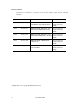
FIGURES 1.1 page MAF3364FC outer view...................................................................................................1-5 1.2 MAG series outer view.....................................................................................................1-5 1.3 Disk/head configuration ...................................................................................................1-6 1.4 FC-AL system configuration ........................................................................
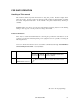
TABLES 2.1 page Function specifications.....................................................................................................2-2 2.2 Environmental/power requirements..................................................................................2-4 3.1 Zone layout and track capacity (MAF3364FC) .................................................................3-3 3.2 Zone layout and track capacity (MAG series) ...................................................................3-3 3.
This page is intentionally left blank.
CHAPTER 1 GENERAL DESCRIPTION 1.1 Standard Features 1.2 Hardware Structure 1.3 System Configuration This chapter describes the feature and configuration of the intelligent disk drives (IDD). MAF3364FC and MAG series intelligent disk drives (IDDs) are high performance large capacity 3.5-inch fixed disk drives with an embedded fibre-channel controller.
1.1 Standard Features (1) Compactness The IDD has the FC-AL controller which supports the Arbitrated Loop (FC-AL) of the fibre channel modes defined by the ANSI standard, embedded in the 3.5-inch fixed disk drive form factor. (2) FC-AL standard The IDD provides not only FC-AL basic functions but also the following features: • • • Arbitration Data frame CRC function Command set which meets the logical specification of the SCSI CCS (Common Command Set for Direct Access Device) requirements (Rev. 4.
(7) 4MB programmable multi-segment data buffer Data is transferred between fibre-channel loop and disk media through the embedded 4MB data buffer in the IDD. This buffer can be divided into maximum 32 areas. This feature provides the suitable usage environment for users.
(14) Programmable data block length Data can be accessed in fixed-block length units. The data block length is programmable, and can at initializing with a multiple of four for the 512 to 528 bytes. (15) Defective block slipping A logical data block can be reallocated in a physical sequence by slipping the defective data block at formatting. This results in high speed contiguous data block processing without a revolution delay due to defective data block.
1.2 Hardware Structure An outer view of the IDD is given in Figures 1.1 and 1.2. The IDD is composed of the disk, head, spindle motor, hermetically sealed disk enclosure (DE) with actuator and air circulation filter, as well as read/write pre-amp with the print card unit (PCA) of the controller. Figure 1.1 MAF3364FC outer view Figure 1.
(1) Disks The disks have an outer diameter of 84 mm (3.31 inch) and inner diameter of 25 mm (0.98 inch). The disks are good for at least 15,000 contact starts and stops. Each model contains following number of disks. MAF3364:10 MAG3182:5 MAG3091:3 (2) Heads The MR (Magnet - Resistive) of the CSS (contact start/stop) type heads are in contact with the disks when the disks are not rotating, and automatically float when the rotation is started. Figure 1.5 shows the configuration of disks and heads.
(4) Actuator The actuator, which uses a rotary voice coil motor (VCM), consumes little power and generates little heat. The head assembly at the end of the actuator arm is controlled and positioned via feedback of servo information in the data. The actuator positions heads on the CCS zone over the disk and is locked by the mechanical lock when the power is off or the spindle motor is stopped.
1.3 System Configuration As the fibre channel mode, the ANSI standard defines three modes: Arbitrated Loop, Fabric and Point-to-Point. This drive supports Arbitrated Loop (FC-AL). Figure 1.4 shows an example of the system configuration. Port B Initiator (Node-1) BC BC Port B Port A BC BC Port A Port B BC BC Port B Drive (Node-4) Drive (Node-2) Drive (Node-3) Port A Figure 1.
CHAPTER 2 SPECIFICATIONS 2.1 Hardware Specifications This chapter describes specifications of the IDD. 2.1 Hardware Specifications 2.1.1 Model name and part number The IDD is provided with various models according to the device type, device capacity, etc. For the model name (type) and product number, refer to the model name/product number list Appendix D.
2.1.2 Function specifications Table 2.1 shows the function specifications of the IDD. Table 2.
MAG3364FC Seek Time MAG series Seek Time (*4) The start time is the time from power on or start command to when the IDD is ready, and stop time is the time for disks to completely stop from power off or stop command. (*5) This value indicates at ready mode.
2.1.3 Environmental specifications Table 2.2 lists environmental and power requirements. Table 2.
2.1.4 Error rate Errors detected during initialization and replaced by alternate block assignments are not included in the error rate. Data blocks to be accessed should be distributed over the disk medium equally. (1) Unrecoverable error rate Errors which cannot be recovered within 63 retries and ECC correction should not exceed 10 per 1015 bits. (2) Positioning error rate Positioning errors which can be recovered by one retry should be 10 or less per 108 seeks. 2.1.
(2) Mean Time To Repair (MTTR) MTTR is the average time taken by a well-trained service mechanic to diagnose and repair a drive malfunction. The drive is designed for a MTTR of 30 minutes or less. (3) Service life The service life is depending on the environment temperature. Therefore, the user must design the system cabinet so that the average DE surface temperature is as possible as low. The service life under suitable conditions and treatment is as follows.
CHAPTER 3 DATA FORMAT 3.1 Data Space 3.2 Logical Data Block Addressing 3.3 Defect Management This chapter explains data space definition, logical data block addressing, and defect management on the IDD. 3.1 Data Space The IDD manages the entire data storage area divided into the following three data spaces.
P: MAF3364FC = 10400 MAG series = 10066 MAC30xxxx = 8690 Figure 3.1 Cylinder configuration Apart from the above logical configuration, the IDD intends to increase the storage capacity by dividing all cylinders into several zones and changing a recording density of each zone. Tables 3.1 and 3.2 show the zone layout and the track capacity.
Table 3.
The default number of cylinders in the user space is 10,200 for MAF3364FC and 9,866 for MAG series. The user, however, can select the number of cylinders to be allocated in the user space by specifying 10,200 for MAF3364FC and 9,866 for MAG series as the maximum and the number of alternate cylinders + 1 as the minimum. The user can also specify the number of logical data blocks to be placed in the user space with the MODE SELECT or MODE SELECT EXTENDED command.
The spare area in each cylinder is placed at the end of the last track as shown in Figure 3.2. These spare sectors are located in the end of the track logically, not necessarily located at the end physically because of track skew or cylinder skew. (Details are explained on Subsection 3.1.3.) Size can be specified by the MODE SELECT or MODE SELECT EXTENDED command. The number of spare sectors per cylinder can be specified exceeding 32.
The interval of the sector pulse (length of the physical sector) is decided by multiple of 20MHz free running frequency. This clock is not equal to the interval of the byte clock for each zone. Therefore, the physical sector length cannot be described with a byte length. 119,700 CLKs*1 (20MHz) Figure 3.
Figure 3.5 Track skew/cylinder skew The number of physical sectors (track skew factor and cylinder skew factor) corresponding to the skew time varies depending on the logical data block length because the track skew and the cylinder skew are managed for individual sectors. The IDD automatically determines appropriate values for the track skew factor and the cylinder skew factor according to the specified logical data block length.
Each sector on the track consists of the following fields: (1) Gaps (G1) The gap length at the time of formatting (initializing) is listed in Figure 3.7. Pattern X'00' is written on the gap field. (2) PLO Sync In this field, pattern X'00' in the length in bytes listed in Figure 3.6 is written. (3) Trailing (TRNG)/Sync Byte (SB) In this field, special pattern in the length in bytes listed in Figure 3.6 is written. (4) LBA The logical block address is written in this field.
3.1.5 Format capacity The size of the usable area for storing user data on the IDD (format capacity) varies according to the logical data block or the size of the spare sector area. Table 3.3 lists examples of the format capacity when the typical logical data block length and the default spare area are used. The following is the general formula to calculate the format capacity.
3.2 Logical Data Block Addressing Independently of the physical structure of the disk drive, the IDD adopts the logical data block addressing as a data access method on the disk medium. The IDD relates a logical data block address to each physical sector at formatting. Data on the disk medium is accessed in logical data block units. The INIT specifies the data to be accessed using the logical data block address of that data.
3.3 Defect Management 3.3.1 Defect list Information of the defect location on the disk is managed by the defect list. The following are defect lists which the IDD manages. • P list (Primary defect list): This list consists of defect location information available at the disk drive shipment and is recorded in a system space. The defects in this list are permanent, so the INIT must execute the alternate block allocation using this list when initializing the disk.
• Alternate sector treatment: The logical data block corresponding to defective sectors is allocated to unused spare sectors in the same cylinder or unused spare sectors in the alternate cylinder. The alternate block allocation is executed by the FORMAT UNIT command, the REASSIGN BLOCKS command, or the automatic alternate block allocation. Refer to OEM Manual–SCSI Logical Specifications–for details of specifications on these commands.
: n represents a logical data block number : Defective sector : Unused spare sector Figure 3.7 Alternate block allocation by FORMAT UNIT command If the data block verifying operation (certification) is not permitted (DCRT flag = 0) in the FORMAT UNIT command, the IDD checks all initialized logical data blocks by reading them out after the above alternate block allocation is made to initialize (format) the disk.
(2) Alternate block allocation by REASSIGN BLOCKS command When the REASSIGN BLOCKS command is specified, the alternate block is allocated to the defective logical data block specified by the initiator by means of alternate sector treatment. If there are unused spare sectors in the same cylinder as the specified defective logical data block, the alternate block is allocated to these unused spare sectors.
(3) Automatic alternate block allocation If the ARRE flag in the MODE SELECT parameter permits the automatic alternate block allocation, the IDD automatically executes the alternate block allocation and data duplication on the defective data block detected during the READ EXTENDED command. This allocation method is the same as with the REASSIGN BLOCKS command (alternate sector treatment). IMPORTANT Automatic alternate block allocation is made only once during the execution of one command.
This page is intentionally left blank.
CHAPTER 4 INSTALLATION REQUIREMENTS 4.1 Mounting Requirements 4.2 Power Supply Requirements 4.3 Connection Requirements This chapter describes the environmental, mounting, power supply, and connection requirements. 4.1 Mounting Requirements 4.1.1 External dimensions Figures 4.1 and 4.2 show the external dimensions of the IDD and the positions of the holes for the IDD mounting screws. Note: Dimensions are in mm.
Figure 4.
Figure 4.
4.1.2 Mounting The permissible orientations of the IDD are shown in Figure 4.3, and the tolerance of the angle is ±5° from the horizontal plane. (a) Horizontal –1 (b) Horizontal –2 (c) Vertical –1 Direction of gravity (d) Vertical –2 (e) Upright mounting –1 Figure 4.3 4.1.
a) Use the frame with an embossed structure, or the like. Mount the IDD with making a gap of 2.5 mm or more between the IDD and the frame of the system. b) As shown in Figure 4.6, the inward projection of the screw from the IDD frame wall at the corner must be 4 mm or less. c) Tightening torque of screw must be secured with 6kg-cm or less. d) Impact caused by the electric driver must be within the device specifications. e) Must be handled on an anti-static mat. Figure 4.
(2) Limitation of side-mounting Mount the side using the screw holes at both the ends as shown in Figure 4.5. Do not use the center hole. Holes for mounting screw 4 3 2 Do not use these holes 1 Figure 4.5 (3) Holes for mounting screw Use these holes (No. 1 to 4) to mount. Limitation of side-mounting Environmental temperature Temperature condition at installed in a cabinet is indicated with ambient temperature measured 3 cm from the disk drive.
Table 4.1 No. Surface temperature check point Measurement point Criteria 1 Center of DE cover 55°C 2 Read channel LSI 83°C 3 VCM/SPM Driver 75°C 4 HDC 85°C 1 2 4 3 Figure 4.
(4) Service clearance area The service clearance area, or the sides which must allow access to the IDD for installation or maintenance, is shown in Figures 4.7. [Surface R] • Hole for mounting screw [Surface P] • Cable connection [Surface Q] • Hole for mounting screw Figure 4.7 (5) Service clearance area External magnetic field The drive should not be installed near the ferromagnetic body like a speaker to avoid the influence of the external magnetic field.
(a) MAF3364FC Air pressure adjustment hole (b) MAG series Air pressure adjustment hole Figure 4.
4.2 Power Supply Requirements (1) Allowable input voltage and current The power supply input voltage measured at the power supply connector pin of the IDD (receiving end) must satisfy the requirement given in Subsection 2.1.3. (For other requirements, see Items (4) and (5) below.) (2) Current waveform (reference) Figure 4.9 shows the waveform of +12 VDC. MAF3364FC Figure 4.
(5) Noise filter To eliminate AC line noise, a noise filter should be installed at the AC input terminal on the IDD power supply unit. The specification of this noise filter is as follows: • • Attenuation: 40 dB or more at 10 MHz Circuit construction: T-configuration as shown in Figure 4.10 is recommended. Figure 4.10 AC noise filter (recommended) 4.3 Connection Requirements 4.3.1 Connector Figure 4.11 shows the locations of connector on the interface model. Interface connector Figure 4.
4.3.2 Interface connector The connector for the fibre channel loop bus is an unshielded SCA-2 connector conforming to SCSI-3 type which has two 20-pin rows spaced 1.27 mm (0.05 inch) apart. Figure 4.12 shows the fibre channel connector. See Section C.5 in Appendix C for signal assignments on the connector. For details on the physical/electrical requirements of the interface signals, refer to Sections 1 Interface Specifications. ESD contact Figure 4.12 SCA2 type interface connector 4.3.
CHAPTER 5 INSTALLATION 5.1 Notes on Handling Drives 5.2 Setting 5.3 Mounting Drives 5.4 Confirming Operations after Installation and Preparation for Use 5.5 Dismounting Drive This chapter describes the notes on handling drives, connections, setting switches and plugs, mounting drives, connecting cables, confirming drive operations after installation and preparation for use, and dismounting drives. 5.
(3) Installation a) When mounting/dismounting the drive, make sure the vibration and shock requirements of "2.1.3 Environmental Specification" are met. b) When removing the spindle motor from the system without stopping it while power is on, pay special attention to shock in particular until the disk drive completely stops running (about 30 seconds). (4) Packaging a) Store the drive in an antistatic vinyl bag with a desiccant (silica gel).
5.2 Setting 5.2.1 Loop ID setting When setting the fibre channel loop ID, use SEL0 to SEL6 of interface connector CN1. IN bit weighting, SEL6 corresponds to the MSB, SEL0 to the LSB, and 126 types of X'00' to X'7D' can be specified as loop IDs. 5.2.2 Mode settings (1) Motor start mode The method for start control of the IDD spindle motor can be set in accordance with Table 5.1. Table 5.
5.3 Mounting Drives 5.3.1 Mounting procedures Since mounting the drive depends on the system cabinet structure, determine the work procedures considering the requirements specific to each system. The general mounting method and items to be checked are shown below. See Subsection 4.1 for the details of requirements for installing the IDD. 1) Fix the drive in the system cabinet with four mounting screws as follows: • The drive has 8 mounting holes (both sides: 2 × 2, bottom: 4).
5.4 Confirming Operations after Installation and Preparation for Use 5.4.1 Confirming initial operations This section describes the operation check procedures after power is turned on. Since the initial operation of the IDD depends on the setting of the motor start mode, check the initial operation by either of the following procedures. (1) Initial operation in the case of setting so that motor starts at powering-on a) When power is turned on, the IDD executes initial self-diagnosis.
IMPORTANT The LED lights during the IDD is executing a command. However, in same commands, the lighting time is only an instant. Therefore, it seems that the LED blinks or the LED remains off. 5.4.2 Checking connection When the initial operation is checked normally after power is turned on, check that the IDD is connected to the loop from the host system. Although checking the connection depends on the structure of the host system, this section describes the general procedures.
Motor starts when power is turned on For Figure 5.2 Figure 5.
Motor starts by START/STOP command Executing time: opprox. 30 seconds To Figure 5.1 Figure 5.
(2) Checking at abnormal end a) When sense data can be obtained with the REQUEST SENSE command, analyze the sense data and retry recovery for a recoverable error. Refer to Chapter 5 of Fibre Channel Interface Specifications for further details. b) Check the setting of the terminals. Note that the checking procedure of loop connection differs depending on the setting of the motor start mode and unit attention report mode. 5.4.
c. Drive parameter (page code = 4) To explicitly specify the number of cylinders in the user space, specify the number in the "number of cylinders" field. Note that the number of alternate cylinders specified by the format parameter (page code = 3) is included in the number of cylinders in the user space. When the number of cylinders need not be specified, specify 0 or the default value in the "number of cylinders" field.
When the parameters are not set or saved with the MODE SELECT or MODE SELECT EXTENDED command, the IDD sets the default values for parameters and operates when power is turned on or after reset. Although the IDD operations are assured with the default values, the operations are not always optimal for the system. To obtain the best performance, set the parameters in consideration of the system requirements specific to the user. This section outlines the parameter setting procedures.
(1) Error recovery parameter The following parameters are used to control operations such as IDD internal error recovery: a.
(2) Disconnection/reconnection parameters (page code = 2) The following parameters are used to optimize the start timing of reconnection processing to transfer data on the loop at a read (READ or READ EXTENDED command) or write operation (WRITE, WRITE EXTENDED, or WRITE AND VERIFY command) of the disk. Refer to Chapter 3 of Fibre Channel Interface Specifications for further details. a.
a.
5.5 Dismounting Drive Since the method and procedure for dismounting the disk drive for replacement of the drive, etc. depends on the locker structure of the system, etc., the work procedure must be determined in consideration of the requirements specific to the system. This section describes the general procedure and notes on dismounting the drive. CAUTION Damage 1. When dismounting the drive which is mounted on the system while power is supplied to it.
This page is intentionally left blank.
CHAPTER 6 DIAGNOSTICS AND MAINTENANCE 6.1 Diagnostics 6.2 Maintenance Information This chapter describes diagnostics and maintenance information. 6.1 Diagnostics 6.1.1 Self-diagnostics The IDD has the following self-diagnostic function. This function checks the basic operations of the IDD. • • Initial self-diagnostics Online self-diagnostics (SEND DIAGNOSTIC command) Table 6.1 lists the contents of the tests performed with the self-diagnostics.
Brief test contents of self-diagnostics are as follows. a. Hardware function test This test checks the basic operation of the controller section, and contains following test. • • • • RAM (microcode is stored) Peripheral circuits of microprocessor (MPU) Memory (RAM) Data buffer b. Seek test This test checks the positioning operation of the disk drive using several seek modes (2 points seek, 1 position sequential seek, etc.).
The IDD does not reply to the loop for up to 2 seconds after the initial self-diagnostics is started. After that, the IDD can accept the I/O operation request correctly, but the received command, except the executable commands under the not ready state (such as INQUIRY, START/STOP UNIT), is terminated with the CHECK CONDITION status (NOT READY [=2]/logical unit not ready [=04-00]) during the interval from the spindle motor becomes stable to the IDD becomes ready.
When an error is detected in the self-diagnostics, the IDD terminates the SEND DIAGNOSTIC command with the CHECK CONDITION status. If an error is detected by a hardware function test at this time, the Fault LED lights up. The INIT should issue the REQUEST SENSE command when the CHECK CONDITION status is posted. The sense data collected by the REQUEST SENSE command indicates the detail information of the error detected in the self-diagnostics.
(1) Interface test The operations of the loop and data buffer on the IDD are checked with the WRITE BUFFER and READ BUFFER commands. (2) Basic operation test The basic operations of the IDD are checked by executing self-diagnosis with the SEND DIAGNOSTIC command (see Subsection 6.1.1). (3) Random/sequential read test The positioning (seek) operation and read operation are tested in random access and sequential access modes with the READ, READ EXTENDED, or VERIFY command.
Note: The "average DE surface temperature" means the average temperature at the DE surface throughout the year when the IDD is operating. (3) Parts that can be replaced in the field The PCA cannot be replaced in the field. The DE cannot be replaced in the field. (4) Service system and repairs Fujitsu has the service system and repair facility for the disk drive. Contact Fujitsu representative to submit information for replacing or repairing the disk drive.
See Section 5.1 for notes on packing and handling when returning the disk drive. 6.2.2 Revision numbers The revision number of the disk drive is represented with a letter and a number indicated on the revision label attached to the DE. Figure 6.1 shows the revision label format. Machine revision Figure 6.
IMPORTANT When the revision number is changed after the drive is shipped from the factory, Fujitsu issues "Engineering Change Request/Notice" in which the new revision number is indicated. When the user changes the revision number, the user should update the revision label as described in item (2) after applying the modification. At shipment Rev. A2 Revising at field Rev. A3 Figure 6.
APPENDIX A LOCATIONS OF CONNECTORS A.1 Locations of Connectors This appendix shows the locations of connectors for 8- and 16-bit SCSIs.
A.1 Locations of Connectors (Rear view) (MAF3364FC) (Rear view) (MAG series) Figure A.
APPENDIX B CONNECTOR SIGNAL ALLOCATION B.1 Interface (FC-SCA) Connector Signal Allocation This appendix describes the connector signal allocation.
B.1 Interface (FC-SCA) Connector Signal Allocation Table B.1 FC-SCA connector: CN1 Pin No. Signal Signal 01 –EN bypass port A +12V charge Pin No.
APPENDIX C MODEL NAMES AND PRODUCT NUMBERS C.1 Model Names and Product Numbers This appendix lists model names (types) and product numbers.
C.1 Model Names and Product Numbers Table C.1 MAF and MAG series model names and product numbers Model name (type) Data block length (at factory shipment) Total storage capacity (user area) Mounting screw Part number Remarks MAF3364FC 512B 36.4 GB #6-32UNC CA01776-B980 1.6-inch height 10,025 rpm 10 disks 19 heads MAG3182FC 512B 18.2 GB #6-32UNC CA01776-B580 1-inch height 10,025 rpm 5 disks 10 heads MAG3091FC 512B 9.
APPENDIX D FIBRE CHANNEL INTERFACE FUNCTIONS D.1 Fibre Channel Interface Function Specifications This appendix lists the fibre channel interface functions provided for the IDD. Refer to the Fibre Channel Logical Interface Specifications for details of each functions.
D.1 Fibre Channel Interface Function Specifications Table D.
Table D.
Table D.
Table D.
Table D.
Table D.
Table D.
Table D.1 Fibre channel interface function specifications (8 of 8) {: Item DIAGNOSTIC FORMAT ID DIAGNOSTIC READ ID Command WRITE RAM (Group 6) READ RAM RECOVER DATA RECOVER ID Defective sector slip processing function Command link function Relative block addressing function Untagged queuing function Tagged command queuing function Contingent Allegiance (CA) Extended Contingent Allegiance (ECA) Command Asynchronous condition notification feature Processing (AEN: async.
This page is intentionally left blank.
Glossary Bus condition: Asynchronous condition for causing SCSI bus status transition. There are two types of bus conditions, ATTENTION and RESET. Bus phase: An SCSI bus state. The SCSI bus is in one of the following phases: BUS FREE, ARBITRATION, SELECTION, RESELECTION, or INFORMATION TRANSFER. The INFORMATION TRANSFER phase is divided into DATA IN, DATA OUT, COMMAND, STATUS, MESSAGE IN, and MESSAGE OUT phases depending on the type of information being transferred. CCS: Common Command Set.
Sense data: Detailed information created by the target when any error is involved in the command termination status. This information is transferred to report the error. Sense key: Four-bit code added to the sense data to identify the class of detected error. Status: One byte of information that is transferred from a target to an initiator on termination of each command to indicate the command termination status. Target: SCSI device which performs I/O initiated by an initiator.
Abbreviations DTE A ACK AEN ALT ARRE ASCII ASG ATN AWG AWRE ACKnowledge Asynchoronous Event Notification ALTernated (block) Automatic Read Reallocation Enabled American Standard Code for Information Interchange ASiGned block ATTeNtion American Wire Gauge Automatic Write Reallocation Enabled Disable Transfer on Error E ECC EER EVPD Error Correction Code Enable Early Recovery Enable Vital Product Data F FG FIFO FmtData FOV FUA Frame Ground First In First Out Format Data Format Options Valid Force Unit
MSG MeSsaGe T Original Equipment Manufacturer TB TPI TRM O OEM Transfer Block Tracks Per Inch TeRMinator P U P list P/N PBdata PC board PCA PER PF PLOSync PMI PR4ML Primary defect list Parts/Number Physical Block data Printed Circuit board Printed Circuit Assembly Post ERror Page Format Phase Lock Oscillator Syncronous Partial Medium Indicator Partial Response class 4 Maximum Likelihood VCM VPD VU AB - 2 Voice Coil Motor Vital Product Data Vendor Unique W Read Continuous Read Cache Disable Requ
This page is intentionally left blank.
&RPPHQWV FRQFHUQLQJ WKLV PDQXDO FDQ EH GLUHFWHG WR RQH RI WKH IROORZLQJ DGGUHVVHV )8-,768 /,0,7(' %XVLQHVV 3ODQQLQJ 6ROLG 6TXDUH (DVW 7RZHU +RULNDZD FKR 6DLZDL NX .
)8-,768 /,0,7(' 5HDGHU &RPPHQW )RUP :H ZRXOG DSSUHFLDWH \RXU FRPPHQWV DQG VXJJHVWLRQV IRU LPSURYLQJ WKLV SXEOLFDWLRQ 3XEOLFDWLRQ 1R 5HY /HWWHU 7LWOH +RZ GLG \RX XVH WKLV SXEOLFDWLRQ" /HDUQLQJ ,QVWDOOLQJ 5HIHUHQFH 0DLQWDLQLQJ &XUUHQW 'DWH ,V WKH PDWHULDO SUHVHQWHG HIIHFWLYHO\" 6DOHV :KDW LV \RXU RYHUDOO UDWLQJ RI WKLV SXEOLFDWLRQ" 9HU\ *RRG )DLU *RRG 3RRU )XOO\ FRYHUHG 2SHUDWLQJ :HOO ,OOXVWUDWHG :KDW LV \RXU RFFXSDWLRQ" 9HU\ 3RRU