SERVIS KVM Multi Platform USB Emulation Server Intelligent Switch for Multi Platform For IA and UNIX servers FS-1004MU FS-1008MU User’s Manual FUJITSU COMPONENT LIMITED 050209
CAUTION 1) 2) 3) 4) 5) 6) 7) 8) 9) This product and document are the copyright of Fujitsu Component Limited. Any unauthorized reprinting, copying, republishing, or modifications to this product or document is prohibited by law. The details of this product and document are subject to revision without notice. If any part of this product or manual is found to be invalid or unclear, please contact our service department. We accept no responsibility for any effect this product may have on other products.
Table of Contents 1 INTRODUCTION ............................................................................................................................................3 1.1. CONVENTIONS ..........................................................................................................................................3 1.2. PACKING LIST............................................................................................................................................3 1.3.
1 Introduction Thank you for your purchase of this KVM Switch (from here on, simply referred to as the "switch device"). This switch device is usable with PC/AT compatible computers and Sun workstations (hereafter referred to as "hosts") under multi-platform configurations. Requiring only a single master set of control devices (monitor, keyboard and mouse), this switch device allows you to operate hosts from a single console setup.
CAUTION 1.3. Safety Instructions Read the “Safety Instructions” before use to ensure proper use of this product. Safety Instructions contained in this section are written for the user to avoid any damage to property or injury to self; please read the following carefully. l During installation and before using the KVM switch, carefully read about environmental conditions in [Specifications] to use the KVM switch correctly.
may fail to function properly depending on the software used. l The PS/2 keyboard and mouse connectors are the same shape. Be sure the colors match to connect them correctly. If they are forced in or connected incorrectly, the switch device may not only function improperly but also may malfunction. l USB connectors of this switch device are for keyboard or mouse only. Other USB devices does not work at all. l Set up the console’s keyboard and mouse with each host correctly.
1.5. Safety Precautions and Limited Warranty Information: Fujitsu’s Products are not designed for use in medical or life support appliances, devices, or systems where malfunction of a Product can reasonably be expected to result in a personal injury.
2. Features l By connecting several hosts (PC/AT compatible computers or Sun workstations) to this switch device, you can save a lot of space by using only one common master console rather than the situation of a console (monitor, keyboard and mouse) for each host that was previously required. However, you cannot hook up both a PS2 keyboard and mouse and a USB keyboard and mouse at the same time to the console.
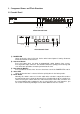
3. Component Names and Their Functions 3.1 Console Panel 1) 4) 3) 2) 5) 8 Port Console Panel 1) 4) 3) 2) 5) 4 Port Console Panel 1) POWER LED Lights up when the host is ON. And, flashes when internal power is low by disconnect an AC cord or blow an internal fuse. 2) Auto Scan Button Press this button when you want to automatically switch between host screens. Pressing it twice stops auto scan. The SELECT LEDs flash (slowly) in order during auto scan.
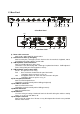
3.2 Rear Panel 6) 7) 13) 5) 9) 8) 10) 11) 12) 8 Port Rear Panel 14) 7) 5) 9) 8) 13) 10) 12) 11) 4 Port Rear Panel 6) Power cable connector Connect to a 100 to 240V AC electric outlet. 7) Connectors for hosts [1 through 8] Connect each port (1 through 8) on this device to the relevant host’s keyboard, mouse and monitor connectors with the special cable. 8) USB keyboard / mouse Connector Connect a USB keyboard / mouse here. (Cannot be used concurrently with a PS/2 type keyboard and mouse.
3.
11
4. Installation Procedure (Rack Setup) 1. Remove the four flathead screws from the left and right sides of the switch device's console panel. 2. Remove the console panel from the switch device, and attach the rack mount bracket (small) to it. (Use the attached M3 screws. (4 pcs.)) 3. Attach the rack mount bracket (large) to the rear panel side of the switch device. (use the attached M3 screws. (6 pcs.)) 4. Detach the console panel connector cable from the console panel before mounting it in the rack.
5. Setup 5.1. Getting started Set the DIP switches to match your chosen environment. Then confirm that the power cable for each host is plugged into an electric outlet and that the power is off. (Confirm connection (a)) 5.2.Connecting the hosts (using single switch device) 1) Connect the first host’s keyboard, mouse connector and CRT connector with the special cable (connect (b)), next connect the switch device’s host port connector (Mini D-Sub 15 pin female) to the special connector (black).
3) After each host and switch device have been connected, connect the keyboard, mouse, and monitor to the [CONSOLE] connectors on the switch device. 4) Attach switch device's AC power cable and then plug it into an electric outlet. 5) After confirming that the connections have been made correctly, start up the attached hosts. 6) Acquire Plug-n-Play data for the monitor. When a monitor is first attached to the switch device, its Plug-n-Play data (EDID data) needs to be acquired by the switch device.
4) After each host and switching device have been connected, connect the keyboard, mouse, and monitor to the [CONSOLE] connectors on the (master) switch device. 5) Attach switch device's AC power cable and then plug it into an electric outlet. 6) After confirming that the connections have been made correctly, start up the attached hosts. 7) Acquire Plug-n-Play data for the monitor.
6. Operation (Host selection) At the beginning, first powered up host is selected automatically. And if some hosts powered up at the same time, a host which connected lower port No. is selected. Also, when the power to a host is turned off while it is selected, the status is preserved. In that case, switch to the host you want to select with the selector buttons or the Hot Keys. In normal operation, there are two methods for selecting a host, the Host Selector Buttons and the OSD display (Hot Key Mode). 6.
6.2.1. Hot Key Mode A Press Ctrl, Alt, Shift once or press the Scroll Lock key twice to go into the Hot Key Mode and the following OSD screen is displayed. Example OSD Screen (probably different to actual screen) a) Screen Details 1.) Center-left of screen (black background) shows the state of the (master) switch device ports. 2.) Center-right of screen (blue background) shows the state of any slave switch device cascade connected to the current channel. 3.
8.) If a cascade-connected master channel or any slave channel is selected, while the key is pressed the OSD screen switches from “3-character master/14-character slave” mode back to “14-character master/5-character slave” mode. The OSD reverts to normal 3/14 mode when the is released. Cascade-connected master channel selected Slave channel selected b) Host Switching No normal keyboard or mouse input is accepted while the hot key mode. [Switching Via Keyboard] 1).
[Switching Via Mouse] The mouse may also be used to control the OSD (instead of the keyboard): 1). Scroll the mouse up & down to select a host (channel) on the left side of the OSD. 2). If a cascade-connected channel is selected, the state of the selected slave device is shown on the right side of the OSD. 3). If a cascade-connected channel is selected, pressing the right mouse key causes control to switch to the right (slave) side of the OSD, with the currently selected cascaded host shown in purple.
C) Setting/Changing Host Names 1). Select the host name to be set/changed using the cursor keys, exactly as if switching. 2). Press the key. 3). The selected name turns yellow, with a single black on yellow character. 4). Use the keyboard to enter the desired name, then press the key to confirm it. Use the key to delete a single character, and the key to backspace. Use the key to cancel an unconfirmed name (revert to original name). 5).
6.2.2. Hot Key Mode B Press the key twice to go into the Hot Key Mode and the following OSD screen appear in the upper-left of the screen. a) Screen Details 1). Selected host name is shown in the OSD in the upper left of the screen. 2). Before switching the text background turns in red. 3). After switching the text background turns in blue, and the Hot Key Mode is exited after the switch is completed. 4). The OSD disappears about 3 seconds later.
6.4. EDID Setting Mode After pressing the ++ keys or double pressing the to activate the Hot Key Mode A, pressing the key changes the display to switch to the Customer Mode: The top line accesses the EDID Setting Mode. The bottom line displays the firmware version currently installed.
We recommend a noninterlaced video signal for the on screen display. CAUTION (However, it is possible to display an interlaced signal with a resolution of 1152 x 864, 1280 x 1024, or 1600 x 1200. However at resolutions lower than this and the display may extend beyond the edges of the screen. When push the Reset Switch, EDID setting is also done automatically.
7. Specifications Item Product ID (Model) Number of Connected Host Devices Selection Method LED Display POWER (Green) SELECT (Green) Host Interfaces PS/2 Keyboard PS/2 Mouse USB Keyboard & Mouse Sun Serial Keyboard & Mouse Host Ports Console Ports Specification FS-1004MU FS-1008MU (KVM switch) (KVM Switch) Max. 4 (more if connections are Max.
8. Optional Accessories (Sold separately) l KVM Special Cables Item Combined Keyboard + Mouse + Monitor Cable (1.8m) Product ID NC14000-B602 NC14000-B102 NC14000-B202 Combined Keyboard + Mouse + NC14000-B603 Monitor Cable (3.0m) NC14000-B103 NC14000-B203 Combined Keyboard + Mouse + NC14000-B605 Monitor Cable (5.0m) NC14000-B105 NC14000-B205 l AC Cables Item For USA For EUROPE For UK l Misc.
9. Troubleshooting Symptom The POWER LED is flashing. Cause The AC cord is not connected to the electric outlet or to the switch device. The AC power is off. Action Connect the AC cord. The internal power fuse has blown. Contact the place of purchase or the support center. Turn on the AC power. The keyboard and mouse do not operate or operate strangely. (Special programmable, cordless or mice with wheels) The keyboard and mouse connections on the Match the port Nos. host are reversed.
n Key layout diagram 1 (ASCII keyboard for PC/AT compatible machines) (1) Esc F1 When connecting to a PC/AT compatible machine F2 F3 F4 F5 F6 F7 F8 F9 F10 F11 F12 Print Screen SysRq * ^ Tab Break Home Page Up Num / Lock End Page Down 7 8 Home 9 4 5 6 1 2 3 Shift Shift Ctrl Alt (2) F1 F2 - .
n Key layout diagram 2 (ASCII keyboard for Sun) (1) When connecting to a Sun workstation Help F1 F2 F3 F4 F5 F6 F7 F8 F9 F10 F11 F12 Print Screen SysRq Scroll Lock Num Lock Tab Ctrl Shift Shift Alt Compose AltGraph F11 F12 + Break Esc Caps Lock - Pause - / 7 8 9 4 5 6 1 2 3 + .
n Appendix: Host name record sheets Record a list of the names of the hosts that attached to your switch device. Master Unit NO. NAME Slave Unit Port.2 NO. NAME Slave Unit Port.4 NO. 1 1 1 2 2 2 3 3 3 4 4 4 5 5 5 6 6 6 7 7 7 8 8 8 Slave Unit Port.1 NO. NAME Slave Unit Port.3 NO. NAME Slave Unit Port.5 NO. 1 1 1 2 2 2 3 3 3 4 4 4 5 5 6 6 7 7 5 6 7 8 8 8 Slave Unit Port.6 NO. NAME Slave Unit Port.7 NO. NAME NAME Slave Unit Port.8 NO.
Declaration of Conformity Model Number : FS-1004MU, FS-1008MU Trade Name : KVM Switch Responsible party : FUJITSU COMPONENT AMERICA, INC. Address : 250 East Caribbean Drive, Sunnyvale,CA94089 Telephone number : (408) 745-4900 This device complies with Part 15 of the FCC Rules. Operation Is subject to the following two conditions : (1) this device may not cause harmful Interference, and (2) this device must accept any Interference received, Including Interference that may cause undesired operation.
This manual is made of recycled paper.