This page is intentionally left blank.
Preface Fujitsu would like to thank you for purchasing our ETERNUS DX60 S2 Disk storage system. The ETERNUS DX60 S2 Disk storage system is designed to be connected to Fujitsu (PRIMEQUEST or PRIMERGY) or non-Fujitsu servers. This manual describes the environmental requirements that are necessary to install and use the ETERNUS DX60 S2 Disk storage system. This manual is intended for use of ETERNUS DX60 S2 Disk storage system in regions other than Japan.
About this Manual Organization This document is composed of the following four chapters: ● Chapter 1 Hardware Configurations This chapter describes the main components and the relative optional products that are installed in the ETERNUS DX60 S2 Disk storage system. ● Chapter 2 ETERNUS DX Disk Storage System Installation This chapter describes the installation specifications, the installation environment, and the power requirements.
About this Manual Warning Notations Warning signs are shown throughout this manual in order to prevent injury to the user and/or material damage. These signs are composed of a symbol and a message describing the recommended level of caution. The following explains the symbol, its level of caution, and its meaning as used in this manual.
Table of Contents Chapter 1 1.1 1.1.1 1.1.2 1.2 1.2.1 1.2.2 1.3 1.4 1.4.1 1.4.2 1.5 Controller Enclosure ......................................................................................... 11 Controllers ................................................................................................................................. 15 Power Supply Units ................................................................................................................... 18 Drive Enclosures ........
Table of Contents Chapter 4 4.1 4.2 4.2.1 4.2.2 4.3 4.3.1 4.3.2 4.3.3 Rack and Optional Product Installation ...............................53 Rack Installation Requirements ....................................................................... 53 Installable Racks .............................................................................................. 54 Fujitsu Racks .............................................................................................................................
List of Figures Figure 1.1 Figure 1.2 Figure 1.3 Figure 1.4 Figure 1.5 Figure 1.6 Figure 1.7 Figure 1.8 Figure 1.9 Figure 1.10 Figure 1.11 Figure 1.12 Figure 1.13 Figure 1.14 Figure 1.15 Figure 1.16 Figure 1.17 Figure 1.18 Figure 1.19 Figure 1.20 Figure 1.21 Figure 1.22 Figure 1.23 Figure 1.24 Figure 1.25 Figure 1.26 Figure 1.27 Figure 1.28 Figure 2.1 Figure 2.2 Figure 2.3 Figure 2.4 Figure 2.5 Figure 2.6 Figure 2.7 Figure 2.8 Figure 2.9 Figure 3.1 Figure 3.2 Figure 3.3 Figure 3.4 Figure 3.5 Figure 3.
List of Figures Figure 3.12 Figure 4.1 Figure 4.2 Figure 4.3 Figure 4.4 Figure 4.5 Power control using a power synchronized unit (when connecting three or more servers) ...... Unit installation area .................................................................................................................. Installation diagram for 2.5" disks.............................................................................................. Installation diagram for 3.5" disks...............................
List of Tables Table 1.1 Table 1.2 Table 1.3 Table 1.4 Table 1.5 Table 1.6 Table 1.7 Table 1.8 Table 1.9 Table 1.10 Table 2.1 Table 2.2 Table 2.3 Table 2.4 Table 2.5 Table 2.6 Table 2.7 Table 2.8 Table 2.9 Table 2.10 Table 2.11 Table 2.12 Table 3.1 Table 3.2 Table 4.1 Table 4.2 Table 4.3 Table 4.4 Host interface port specifications............................................................................................... DI port specifications ..........................................................
Chapter 1 Hardware Configurations This chapter explains hardware configurations for the ETERNUS DX Disk storage system. 1.1 Controller Enclosure This section explains the main components in the controller enclosure. The controller enclosure contains disks installed in the front, and controllers and power supply units in the rear. Since the power supply units are redundant, operations can continue even if one of them fails. There are two models: a single-controller type and a dual-controller type.
Chapter 1 Hardware Configurations 1.1 Controller Enclosure ● Rear view • Single-controller type LAN (MNT) port LAN (RMT) port Cover PWC port Controller (CM#0) Power supply unit (PSU#1) Power supply unit (PSU#0) Host interface ports (0 (Left), 1 (Right)) DI (OUT) port Figure 1.2 Rear view of a 2.
Chapter 1 Hardware Configurations 1.1 Controller Enclosure ● Top view Figure 1.4 Top view of a 2.5" type controller enclosure ● Side view Figure 1.5 Side view of a 2.5" type controller enclosure ■ External views of a 3.5" type controller enclosure ● Front view Figure 1.6 Front view of a 3.5" type controller enclosure (with front cover) 3.5" disk Figure 1.7 Front view of a 3.
Chapter 1 Hardware Configurations 1.1 Controller Enclosure ● Rear view • Single-controller type LAN (MNT) port LAN (RMT) port Cover PWC port Controller (CM#0) Power supply unit (PSU#1) Power supply unit (PSU#0) Host interface ports (0 (Left), 1 (Right)) DI (OUT) port Figure 1.8 Rear view of a 3.
Chapter 1 Hardware Configurations 1.1 Controller Enclosure ● Top view Figure 1.10 Top view of a 3.5" type controller enclosure ● Side view Figure 1.11 Side view of a 3.5" type controller enclosure 1.1.1 Controllers The controller contains a CPU, cache memory, System Capacitor Unit (SCU), non-volatile memory, host interface ports, drive interface (DI) ports, and LAN ports. The controller controls all operations in the ETERNUS DX Disk storage system.
Chapter 1 Hardware Configurations 1.1 Controller Enclosure ■ Host interface ports Host interface ports are used to connect controllers to servers. Two host interface ports can be installed in the controller of an ETERNUS DX Disk storage system. FC, iSCSI, and SAS are available as host interface. ● FC model FC ports (0 (Left), 1 (Right)) Figure 1.12 Host interface port (FC model) ● iSCSI model iSCSI ports (0 (Left), 1 (Right)) Figure 1.
Chapter 1 Hardware Configurations 1.1 Controller Enclosure ■ Drive interface ports A DI port is used to connect a drive enclosure. The following table shows the DI port specifications. Table 1.2 DI port specifications Interface SAS Transfer speed (max.) Connector type 3Gbit/s Number of ports for each controller miniSAS (SFF8088) 1 ■ LAN ports Two LAN ports (RJ-45) are installed in each controller.
Chapter 1 Hardware Configurations 1.2 Drive Enclosures 1.1.2 Power Supply Units The power supply unit transforms input AC power from a power socket to DC power and supplies power to each component. Two power supply units are installed in each controller enclosure. Each power supply unit contains fans. Figure 1.15 Power supply unit (controller enclosure) 1.2 Drive Enclosures This section explains the main components in the drive enclosure.
Chapter 1 Hardware Configurations 1.2 Drive Enclosures ● Rear view • Single-expander type This is not used. DI (IN) port Cover Expander (EXP#0) Power supply unit (PSU#1) Power supply unit (PSU#0) Figure 1.18 Rear view of a drive enclosure (single-expander type) • Dual-expander type These are not used. DI (IN) ports Expander (EXP#0) Expander (EXP#1) Power supply unit (PSU#0) Power supply unit (PSU#1) Figure 1.19 Rear view of a drive enclosure (dual-expander type) ● Top view Figure 1.
Chapter 1 Hardware Configurations 1.2 Drive Enclosures ● Side view Figure 1.21 Side view of a drive enclosure 1.2.1 Expanders The expander is a component that controls the interaction between the controller and the disks. DI (IN) port This is not used. Figure 1.22 Expander (drive enclosure) ■ Drive interface ports A DI port is used to connect a controller enclosure. The following table shows the DI port specifications. Table 1.5 DI port specifications Interface SAS 1.2.2 Transfer speed (max.
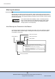
Chapter 1 Hardware Configurations 1.3 Enclosure Connection Path 1.3 Enclosure Connection Path For a dual-controller type, a controller enclosure (CE) is connected to a drive enclosure (DE) with multiple paths. A drive enclosure has two independent DI ports. Path redundancy is maintained by connecting the drive enclosure to two controllers directly. This configuration allows operation to continue even if one of the connection paths fails. DE DI DI DI DI CE DI: Drive Interface port Figure 1.
Chapter 1 Hardware Configurations 1.4 Disks 1.4 Disks The following disks can be installed in a controller enclosure and drive enclosure. 1.4.1 2.5" Disks The following table shows the 2.5" disk specifications. Table 1.6 2.5" disk specifications Disk name DI SAS disks Serial Attached SCSI (3Gbit/s) Nearline SAS disks 1.4.2 Storage media Storage capacity Speed Hard disk 300GB, 450GB, 600GB, 900GB 10,000rpm Hard disk 1TB 7,200rpm 3.5" Disks The following table shows the 3.
Chapter 1 Hardware Configurations 1.5 Power Distribution Units (Only for Regions Other than EMEA&I) 1.5 Power Distribution Units (Only for Regions Other than EMEA&I) There are two sizes for power distribution units: 1U and 2U. A power distribution unit is an option to connect power supply units to power outlets when power sockets are limited. ■ Power distribution unit for DX60 S2 (AC200-240V, 1U, Max 2 enclosures connection) There are four outlets and two inlets.
Chapter 1 Hardware Configurations 1.5 Power Distribution Units (Only for Regions Other than EMEA&I) ■ Power distribution unit for DX60 S2 (AC200-240V, 2U, Max 6 enclosures connection) There are 12 outlets. Outlets (OUTPUT) Figure 1.27 Power distribution unit (AC200-240V, 2U, Max 6 enclosures connection) The following table shows the specifications of a power distribution unit and the AC cables that are provided. Table 1.
Chapter 1 Hardware Configurations 1.5 Power Distribution Units (Only for Regions Other than EMEA&I) The following table shows the specifications of a power distribution unit and the AC cables that are provided. Table 1.
Chapter 2 ETERNUS DX Disk Storage System Installation This chapter explains the installation of the ETERNUS DX Disk storage system. 2.1 Installation Specifications 2.1.1 ETERNUS DX60 S2 The following table shows the specifications of the ETERNUS DX60 S2. Table 2.1 ETERNUS DX60 S2 installation specifications ETERNUS DX60 S2 Item Controller enclosure Dimensions (W × D × H) Maximum weight (*2) 2.5" disk configuration 3.
Chapter 2 ETERNUS DX Disk Storage System Installation 2.
Chapter 2 ETERNUS DX Disk Storage System Installation 2.2 Package Size 2.2 Package Size The ETERNUS DX Disk storage system is shipped in cardboard boxes. These boxes may not fit through some doorways or elevators. To make sure that the ETERNUS DX Disk storage system can be moved to the installation site, carefully check the transport route information. Refer to "2.1 Installation Specifications" (page 26) for the maximum weight of each enclosure.
Chapter 2 ETERNUS DX Disk Storage System Installation 2.3 Installation Area 2.3 Installation Area This section explains the installation area and the service area that are required for an ETERNUS DX Disk storage system that is installed in a Fujitsu 19-inch rack. Secure service areas that are 800mm or more in the front and rear of the ETERNUS DX Disk storage system. The size of the side areas varies depending on the rack specifications.
Chapter 2 ETERNUS DX Disk Storage System Installation 2.4 Installation Environment 2.4 Installation Environment Sufficient consideration of the installation environment should be taken to ensure proper use of the ETERNUS DX Disk storage system. Using the ETERNUS DX Disk storage system in an environment that does not satisfy the installation environment requirements may cause a failure to occur with the ETERNUS DX Disk storage system. 2.4.
Chapter 2 ETERNUS DX Disk Storage System Installation 2.5 Outlet/Socket Specifications 2.4.3 Load Bearing Capacity for Floors Make sure that the following relationship between the load bearing capacity of the floor and the weight of the ETERNUS DX Disk storage system is maintained.
Chapter 2 ETERNUS DX Disk Storage System Installation 2.5 Outlet/Socket Specifications ■ Power cords ● Power cords supplied with the ETERNUS DX Disk storage system (for the EMEA&I region) Table 2.3 Specifications for power cords supplied with the ETERNUS DX Disk storage system (for the EMEA&I region) Usage Plug type Socket type Used for connection between the ETERNUS DX Disk storage system and the socket (IEC60320-C13 ↔ IEC60320-C14G) IEC60320-C14G IEC60320-C13 Cable length 2.
Chapter 2 ETERNUS DX Disk Storage System Installation 2.5 Outlet/Socket Specifications ■ Power distribution units (only for regions other than EMEA&I) ● Power distribution unit for DX60 S2 (AC200-240V, 1U, Max 2 enclosures connection) Table 2.5 Specifications for power distribution unit for DX60 S2 (AC200-240V, 1U, Max 2 enclosures connection) Output Input Outlet type Plug type Socket type IEC60320-C13 NEMA L6-15P NEMA L6-15R Cable length 4.
Chapter 2 ETERNUS DX Disk Storage System Installation 2.5 Outlet/Socket Specifications 2.5.2 Required Number of Outlets/Sockets The number of power outlets/sockets required to install the ETERNUS DX Disk storage system depends on the number of drive enclosures and power distribution units. It is recommended that the power cord of a drive enclosure is connected to the power distribution unit that is installed in the same rack.
Chapter 2 ETERNUS DX Disk Storage System Installation 2.5 Outlet/Socket Specifications ● Power distribution unit (1U) Up to two enclosures can be connected to a single power distribution unit (1U). Output (4 outlets) Input (2 sockets) Figure 2.2 Power distribution unit (1U) ● Power distribution unit (2U) - Power distribution unit for DX60 S2 (AC200-240V, 2U, Max 6 enclosures connection) Up to six enclosures can be connected.
Chapter 2 ETERNUS DX Disk Storage System Installation 2.6 Circuit Protectors 2.6 Circuit Protectors Protection coordination must be secured between the distribution board circuit protectors and the ETERNUS DX Disk storage system or power distribution units to protect the ETERNUS DX Disk storage system by blocking the failed circuit immediately when a power supply input error occurs. Distribution board circuit protectors must satisfy the following required conditions and breaking characteristics. 2.6.
Chapter 2 ETERNUS DX Disk Storage System Installation 2.6 Circuit Protectors Breaking Characteristics ■ For power distribution unit (2U) connection The breaking characteristics (*1) of distribution board circuit protectors must be slower than the values shown in Figure 2.4 or equivalent to D (IEC898). *1: Relationship between the size of excess current and operation time MAY TRIP 10000 DELAY 63 1000 TIME IN SECONDS 2.6.2 100 10 1 .1 .01 .
Chapter 2 ETERNUS DX Disk Storage System Installation 2.6 Circuit Protectors PSU DE #01 PSU PSU CE PSU ETERNUS DX Disk storage system CP CP Power distribution unit Line 0 Line 1 CP CP Distribution board Distribution board To power supply facility To power supply facility CP: Circuit Protector Figure 2.
Chapter 2 ETERNUS DX Disk Storage System Installation 2.6 Circuit Protectors Table 2.11 Delay 200E Power distribution unit (1U) breaking characteristics (Trip time (sec.)) 100% 125% 150% 200% 400% 600% 800% 1000% No Trip 45 to 500 15 to 250 6 to 90 0.7 to 15 0.008 to 5 0.006 to 0.4 0.004 to 0.
Chapter 2 ETERNUS DX Disk Storage System Installation 2.6 Circuit Protectors ■ For direct (no power distribution unit) connection The breaking characteristics of distribution board circuit protectors must be slower than the values shown in Figure 2.8 or equivalent to D (IEC898). CURVE 200E 1000 TIME IN SECONDS 100 10 1 0.1 0.01 0.001 100 200 300 400 500 600 700 800 900 1000 125 PERCENT LOAD (%) 150 Figure 2.8 ETERNUS DX Disk storage system (PSU) breaking characteristics (graph) Table 2.
Chapter 3 Connections This chapter explains connections for the ETERNUS DX Disk storage system. 3.1 Host Connections FC, iSCSI, and SAS host interface models are available for the ETERNUS DX60 S2. The server and the ETERNUS DX Disk storage system can be connected directly or via a switch. 3.1.1 Host Interfaces This section describes each host interface. ■ FC (Fibre Channel) FC supports two connection topologies: Fibre Channel Arbitrated Loop (FC-AL) and Fabric.
Chapter 3 Connections 3.1 Host Connections Table 3.1 Ethernet frame capacity (Jumbo Frame settings) Jumbo Frame settings Ethernet frame capacity Enabled Up to 9000 bytes Disabled Up to 1500 bytes • Confirm that the connected device supports Jumbo Frame before enabling Jumbo Frame. • Server-side CPU load can be reduced by using Jumbo Frame. However, I/O performance may be reduced by 10% to 30%. • When using a LAN switch that supports the Flow Control function, disable the Flow Control function.
Chapter 3 Connections 3.1 Host Connections Server Server HBA Port HBA Port Port Port CM#0 CM#1 ETERNUS DX Disk storage system Figure 3.1 Single path connection (direct connection) Server Server HBA Server HBA HBA Switch Port Port Port CM#0 Port CM#1 ETERNUS DX Disk storage system Figure 3.2 Single path connection (switch connection) ■ Multipath configuration A multipath configuration connects the ETERNUS DX Disk storage system to a server via multiple paths (multipath).
Chapter 3 Connections 3.1 Host Connections Server Server HBA HBA Port HBA Port Port HBA Port CM#0 CM#1 ETERNUS DX Disk storage system Figure 3.3 Multipath connection (direct connection) Server Server HBA HBA HBA HBA Switch Port Server HBA HBA Switch Port Port CM#0 Port CM#1 ETERNUS DX Disk storage system Figure 3.
Chapter 3 Connections 3.2 LAN Connection 3.2 LAN Connection The ETERNUS DX Disk storage system requires a LAN connection for operation management. In addition, information such as ETERNUS DX Disk storage system failures is notified to the remote support center. Make sure to connect each controller to the LAN for operation management. Administration terminal SNMP manager NTP server Mail server Remote support center ETERNUS DX Disk storage system Figure 3.
Chapter 3 Connections 3.3 Power Supply Connection ■ LAN for remote support Various failures that occur in the ETERNUS DX Disk storage system are notified to the remote support center. Remote support connection can be separated from the LAN for operation management. 3.3 Power Supply Connection Connect the power cords (AC cables) of the ETERNUS DX Disk storage system to the power sockets, the UPS sockets, or the power control unit sockets. Refer to "2.
Chapter 3 Connections 3.3 Power Supply Connection Power distribution unit ETERNUS DX Disk storage system UPS Line 0 PSU Line 1 PSU UPS Figure 3.7 Dual-line power supply when connecting to UPS units Line 0 Power supply facility Power distribution unit ETERNUS DX Disk storage system PSU PSU Figure 3.8 Single-line power supply when connecting to power sockets Power distribution unit UPS ETERNUS DX Disk storage system PSU Line 0 PSU Figure 3.
Chapter 3 Connections 3.3 Power Supply Connection 3.3.2 UPS Connection It is recommended that an Uninterruptible Power Supply System (UPS) be used as the power supply source for the ETERNUS DX Disk storage system to cope with power outages and momentary voltage drops in the normal power supply. Note that when connecting an ETERNUS DX Disk storage system to a UPS with one power supply line, the total value of the power requirements for all the enclosures must not exceed the UPS output capacity.
Chapter 3 Connections 3.4 Power Synchronized Connections 3.4 Power Synchronized Connections This section describes connections to automatically control powering the ETERNUS DX Disk storage system on and off with a server. ■ Power synchronized unit A power synchronized unit enables the ETERNUS DX Disk storage system to be powered on and off with a server.
Chapter 3 Connections 3.4 Power Synchronized Connections • When connecting one or two servers Turns on: 1 Turns off: 2 UPS setting Turns on: 2 Turns off: 1 Server UPS management software UPS Power synchronized unit 4 PWC RS232C cable An instruction is issued to turn on/off the ETERNUS DX Disk storage system when AC output/no AC output is detected. ETERNUS DX Disk storage system PWC 3 Figure 3.
Chapter 3 Connections 3.4 Power Synchronized Connections • When connecting three or more servers Turns on: 1 Turns off: 2 Turns on: 2 Turns off: 1 Server#1 UPS unit for Server#1 Server#3 UPS unit for Server#3 AC sensor unit#1 Server#0 UPS unit for Server#0 Server#2 UPS unit for Server#2 AC sensor unit#0 Power synchronized PWC PWC ETERNUS DX Disk storage system 4 PWC 3 ETERNUS DX Disk storage system 4 PWC Figure 3.
Chapter 3 Connections 3.4 Power Synchronized Connections ● Powering off sequence 1 Shutdown of all the servers 2 Shutdown of all the server UPS units 3 Issuance of command to turn off the ETERNUS DX Disk storage system from the power synchronized unit 4 ETERNUS DX Disk storage system shutdown Refer to the manual that is provided with a power synchronized unit for details about connection configurations with power synchronized units and required settings.
Chapter 4 Rack and Optional Product Installation This chapter explains the requirements for installation of racks and the optional products for an ETERNUS DX Disk storage system. 4.1 Rack Installation Requirements This section explains the requirements for installing the ETERNUS DX Disk storage system in a 19-inch rack. Enclosures are installed in the following order (from bottom to top). The center of gravity must be taken into consideration to prevent a rack from toppling over.
Chapter 4 Rack and Optional Product Installation 4.2 Installable Racks 4.2 Installable Racks This section explains the racks in which the ETERNUS DX Disk storage system can be installed. 4.2.1 Fujitsu Racks The ETERNUS DX Disk storage system can be installed in a Fujitsu 19-inch rack. For information about whether the ETERNUS DX Disk storage system can be installed in an EOLed rack or not, contact your sales representative. 4.2.
Chapter 4 Rack and Optional Product Installation 4.2 Installable Racks (1) (2) (3) Rack rails ETERNUS DX Disk storage system (4) Rack front door Rack pillars Figure 4.1 Unit installation area Table 4.
Chapter 4 Rack and Optional Product Installation 4.3 Standard Installation Rules Before Shipment (Only for Regions Other than EMEA&I) 4.3 Standard Installation Rules Before Shipment (Only for Regions Other than EMEA&I) This section explains the rules for combining the following optional products and standard installation rules that apply before shipment from the factory. • Drive enclosures • Disks 4.3.1 Drive Enclosures This section explains the installation rules for a drive enclosure. ■ 2.
Chapter 4 Rack and Optional Product Installation 4.3 Standard Installation Rules Before Shipment (Only for Regions Other than EMEA&I) 4.3.2 Disks This section explains the installation rules for disks. ■ 2.5" disks The following table shows the priority order of 2.5" disk installation. Table 4.3 Priority order of 2.
Figure 4.2 Slot#23 Slot#22 Slot#21 Slot#20 Slot#19 Slot#18 Slot#17 Slot#16 Slot#15 Slot#14 Slot#13 Slot#11 Slot#12 Slot#10 Slot#9 Slot#8 Slot#7 Slot#6 Slot#5 Slot#4 Slot#3 Slot#2 Slot#1 Slot#0 Chapter 4 Rack and Optional Product Installation 4.3 Standard Installation Rules Before Shipment (Only for Regions Other than EMEA&I) Installation diagram for 2.5" disks ■ 3.5" disks The following table shows the priority order of 3.5" disk installation. Table 4.4 Priority order of 3.
Chapter 4 Rack and Optional Product Installation 4.3 Standard Installation Rules Before Shipment (Only for Regions Other than EMEA&I) Priority order Type Disk capacity/quantity RAID level 16 1TB/7.2krpm × 2 RAID1 17 1TB/7.2krpm × 6 RAID1+0 18 1TB/7.2krpm × 6 RAID5 19 1TB/7.2krpm × 6 RAID6 20 1TB/7.2krpm × 1 Hot spare 21 2TB/7.2krpm × 2 RAID1 2TB/7.2krpm × 6 RAID1+0 2TB/7.2krpm × 6 RAID5 2TB/7.2krpm × 6 RAID6 25 2TB/7.2krpm × 1 Hot spare 26 3TB/7.2krpm × 2 RAID1 22 3.
Chapter 4 Rack and Optional Product Installation 4.3 Standard Installation Rules Before Shipment (Only for Regions Other than EMEA&I) CE#0 A A B B B B B B C C D D D D D D H1 Optional disks A: 2.5" SAS (300GB, RAID1) B: 2.5" SAS (300GB, RAID1+0) C: 2.5" SAS (450GB, RAID1) D: 2.5" SAS (600GB, RAID6) H1: 2.5" SAS (600GB, hot spare) Figure 4.4 Disk installation example at shipment (2.5" type controller enclosure) ■ 3.
ETERNUS DX60 S2 Disk storage system User's Guide -Site PlanningP3AM-5492-04ENZ0 Date of issuance: May 2012 Issuance responsibility: FUJITSU LIMITED • The content of this manual is subject to change without notice. • This manual was prepared with the utmost attention to detail. However, Fujitsu shall assume no responsibility for any operational problems as the result of errors, omissions, or the use of information in this manual.