
Computer Hardware User Manual
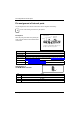
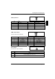
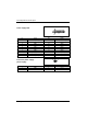
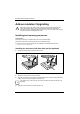
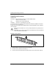
Table Of Contents
- Title
- Übersicht/Overview Mainboard D1740
- Contents
- Mainboard D1740
- Brief instructions on installing mainboard
- Interfaces and connectors
- Settings with switches and jumpers
- Add-on modules / Upgrading
- Annex
- Error messages
- Glossary
Pin assignment of internal ports
Pin assignment of internal ports
The pin assignment of some internal connections is shown in English in the following.
i
Some of the following connectors may be optional!
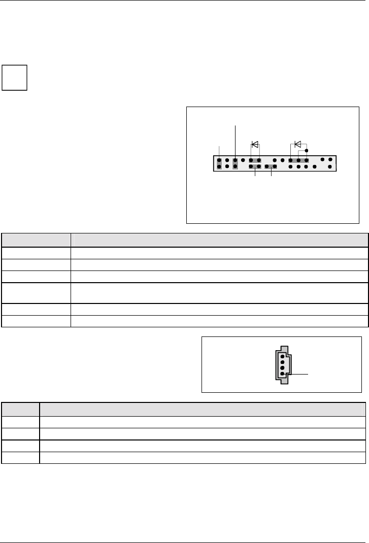
Front panel
Watch the poling of the LEDs. The positive pole
of the connection cables is often indicated with a
coloured wire.
1) Cable is not included in the delivery scope.
2) 2-pin or 3-pin connector possible
1
2
HD-LED
1)
Power On/Off
Recovery
Reset
1)
Power On
LED
1) 2)
Password
Connection Note
Reset
Power On/Off
HD LED
Power On LED I Indicates the system state APM or ACPI (see chapter "APM and ACPI system
status, energy-saving modes").
Password see "Settings with switches and jumpers" chapter
Recovery see "Settings with switches and jumpers" chapter
AUX-Audio In or
CD-ROM Audio Conector
1
Pin Signal
1 Left CD audio input
2 CD GND
3 CD GND
4 Right CD audio input
12 - English A26361-D1740-Z120-1-6319, Edition: 3