
AOU36RLX Installation Manual


En-6
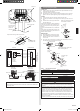
5.5. Vacuum
(1) Remove the cap, and connect the gauge manifold and the vacuum pump to the
charging valve by the service hoses.
(2) Vacuum the indoor unit and the connecting pipes until the pressure gauge
indicates -0.1 MPa (-76 cmHg).
(3) When -0.1 MPa (-76 cmHg) is reached, operate the vacuum pump for at least
60 minutes.
(4) Disconnect the service hoses and t the cap to the charging valve to the specied
torque.
(5) Remove the blank caps, and fully open the spindles of the 3-way (Liquid) and 3-way
(Gas) valves with a hexagon wrench [Torque: 6~7 N·m (60 to 70 kgf·cm)].
(6) Tighten the blank caps of the 3-way (Liquid) valve and 3-way (Gas) valve to the
specied torque.
Tightening torque
Blank
cap
9.52 mm (3/8 in.) 20 to 25 N·m (200 to 250 kgf·cm)
15.88 mm (5/8 in.) 30 to 35 N·m (300 to 350 kgf·cm)
Charging port cap 12.5 to 16 N·m (125 to 160 kgf·cm)
Blank cap
Charging port
Cap
Service hose
with valve core
Outdoor unit
3-way valve
Connecting pipe
Hexagon wrench
Use a 4 mm
hexagon wrench.
Lo
Hi
Service hose
Gauge manifold
Vacuum pump
CAUTION
Use a clean gauge manifold
and charging hose for R410A
exclusively.
CAUTION
Do not purge the air with refrigerants, but use a vacuum pump to vacuum the
installation.
There is no extra refrigerant in the outdoor unit for air purging.
Use a vacuum pump and gauge manifold and charging hose for R410A exclusively.
Using the same vacuum for different refrigerants may damage the vacuum pump or the
unit.
ADDITIONAL CHARGE
CAUTION
When moving and installing the air conditioner, do not mix gas other than the
specied refrigerant R410A inside the refrigerant cycle.
When charging the refrigerant R410A, always use an electronic balance for refrig-
erant charging (to measure the refrigerant by weight).
When charging the refrigerant, take into account the
slight change in the composition of the gas and liquid
phases, and always charge from the liquid phase side
whose composition is stable.
R410A
Liquid
Gas
Add refrigerant from the charging valve after the comple-
tion of the work.
If the units are further apart than the maximum pipe length, correct operation can-
not be guaranteed.
GAS LEAKAGE INSPECTION
CAUTION
After connecting the piping, check the all joints for gas leakage with gas leak detector.
When inspecting gas leakage, always use the vacuum pump for pressure. Do not use
nitrogen gas.
5.7. TEST RUN
•
Perform test operation and check items below.
•
For the test operation method, refer to the operating manual.
•
The outdoor unit, may not operate, depending on the room temperature. In this
case, keep on pressing the MANUAL AUTO button of the indoor unit for more than
10 seconds. The operation indicator lamp and timer indicator lamp will begin to ash
simultaneously during cooling test run. Then, heating test run will begin in about three
minutes when HEAT is selected by the remote control operation. (Please follow the
operating manual for remote control operation.)
•
To end test operation, keep on pressing the MANUAL AUTO button of the indoor unit for
more than 3 seconds.
(When the air conditioner is run by pressing the MANUAL AUTO button, the OPERA-
TION indicator lamp and TIMER indicator lamp of the indoor unit will simultaneously
ash slowly.)
OUTDOOR UNIT
(1) Is there any abnormal noise and vibration during operation?
(2) Will noise, wind, or drain water from the unit disturb the neighbors?
(3) Is there any gas leakage?
CAUTION
Always turn on the power 12 hours prior to the start of the operation in order to
ensure compressor protection.
6. PUMP DOWN
6.1. Pump down
PUMP DOWN OPERATION (FORCED COOLING OPERATION)
To avoid discharging refrigerant into the atmosphere at the time of relocation or disposal,
recover refrigerant by doing the forced cooling operation according to the following proce-
dure.
(1) Connect the charging hose by connecting charging hose to the gauge manifold to the
charging port of 3-way valve (Gas).
(2) Conduct preliminary operation for 5 to 10 minutes using the forced cooling operation.
Start the forced cooling operation. Keep on pressing the MANUAL AUTO button of
the indoor unit for more than 10 seconds. The operation indicator lamp and timer
indicator lamp will begin to flash simultaneously during test run. (The forced cooling
operation cannot start if the MANUAL AUTO button is not kept on pressing for more
than 10 seconds.)
(3) Close the valve stem of 3-way valve (Liquid) completely.
(4) Close the valve stem of 3-way valve (Gas) when the reading on the compound pres-
sure gauge becomes 0.05~0 MPa (0.5~0 kg/cm
2
).
(5) Stop the operation.
• Press the START/STOP button of the remote controller to stop the operation.
• Press the MANUAL AUTO button when stopping the operation from the indoor unit
side.
(It is not necessary to press down for more than 10 seconds.)
CAUTION
Please check the refrigerant circuit for any leaks before starting the pump down
operation.
Do not proceed with the pump down operation if there is no refrigerant left in the
circuit due to bent or broken piping
During the pump down operation, be sure to turn off the compressor before
removing the refrigerant piping.
9374995356_IM.indb 6 11/20/2014 10:31:32 AM