
AOU36RLX Installation Manual


En-5
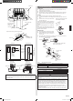
5.4. Connecting the piping
CONNECTION
(1) Install the outdoor unit wall cap (supplied with the optional installation set or pro-
cured at the site) to the wall pipe.
(2) Connect the outdoor unit and indoor unit piping.
(3) After matching the center of the are surface and tightening the nut hand tight,
tighten the nut to the specied tightening torque with a torque wrench. (Table 1)
FLARING
(1) Cut the connection pipe to the necessary length with a pipe cutter.
(2) Hold the pipe downward so that cuttings will not enter the pipe and remove the
burrs.
(3) Insert the are nut onto the pipe and are the
pipe with a aring tool.
Insert the are nut (always use the are nut attached
to the indoor and outdoor units respectively) onto
the pipe and perform the flare processing with a
are tool.
Use the special R410A are tool, or the R22 are
tool.
When using the conventional are tool, always use
an allowance adjustment gauge and secure the A
dimension shown in table 2.
BENDING PIPES
(1)
When bending the pipe, be careful not to crush it.
(2)
To prevent breaking of the pipe, avoid sharp bends.
Bend the pipe with a radius of curvature of
70 mm or over.
(3) If the copper pipe is bend the pipe or pulled to often, it will become stiff. Do not
bend the pipes more than three times at one place.
Holding spanner
90°
Body side
Torque wrench
To prevent gas leakage, coat the are
surface with refrigerator oil.
3-way valve
(Liquid)
Flare nut
Connection pipe
(Liquid)
Connection pipe
(Gas)
Flare nut
3-way valve
(Gas)
Table 1 Flare nut tightening torque
Flare nut [mm (in.)]
Tightening torque [N·m (lbf·ft)]
9.52 (3/8) dia. 32 to 42 (23.6 to 31.0)
15.88 (5/8) dia. 63 to 75 (46.5 to 55.3)
Table 2 Pipe outside diameter
Pipe outside diameter [mm (in.)]
A [mm (in.)]
Flare tool for R410A, clutch type
9.52 (3/8) 0 to 0.5 (0 to 1/32)
15.88 (5/8) 0 to 0.5 (0 to 1/32)
CAUTION
Fasten a are nut with a torque wrench as instructed in this manual. If fastened too
tight, the are nut may be broken after a long period of time and cause a leakage of
refrigerant.
Install heat insulation around both the gas and liquid pipes. Failure to do so may cause
water leaks.
Use heat insulation with heat resistance above 248 °F. (Reverse cycle model only)
In addition, if the humidity level at the installation location of the refrigerant piping is
expected to exceed 70%, install heat insulation around the refrigerant piping. If the
expected humidity level is 70-80%, use heat insulation that is 15 mm or thicker and if
the expected humidity exceeds 80%, use heat insulation that is 20 mm or thicker.
If heat insulation is used that is not as thick as specied, condensation may form on the
surface of the insulation.
In addition, use heat insulation with heat conductivity of 0.045 W/(m·K) or less (at 68 °F).
Check if [L] is ared uniformly and
is not cracked or scratched.
Die
A
Pipe
GG
GG
Control box
Terminal
Power supply cable
Connection cable
(indoor unit and
outdoor unit
connection cable)
Cable clamp
30 mm (1-3/16")
Keep the earth wire longer than the other wires.
Power supply cable
or connection cable
Earth wire
40 mm (1-9/16")
or more
1
2
3
1
2
3
GG
L1
L2
INDOOR
INDOOR UNIT
OUTDOOR UNIT
TERMINAL
DISCON-
NECT
SWITCH
(Locally
procured )
Grounding
line
Power lines
Control line
TERMINAL
Power supply line
Single-phase, 230/208 V
Power supply line
G
1 2
3
4
1 2
3
L1 L2
G
G
Earth screw
Earth screw
Earth screw
Disconnect switch
Indoor unit
terminal block
Outdoor unit
terminal block
NOTE:
Factory installed protective inline fuses for indoor units’ conductors are installed on the
Power Supply PCB.
9374995356_IM.indb 5 11/20/2014 10:31:32 AM