
AOU36RLX Installation Manual


En-3
CAUTION
Do not install where there is the danger of combustible gas leakage.
Do not install near heat sources.
If children may approach the unit, take preventive measures so that they cannot reach
the unit.
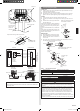
4. INSTALLATION DIAGRAM
4”(10 cm) or over
24”(60 cm) or over
4”(10 cm) or over
24”(60 cm) or over
10”
(25 cm)
or over
2”(5 cm) or over
[OUTDOOR UNIT]
(1) Outdoor unit to be fasten with bolts at the four places indicated by the arrows without
fail.
Bottom side
Drain cap
mounting place
Drain pipe
mounting place
650 mm
(25-19/32")
4-ø 12 hole
370 mm
(14-9/16")
(2) Fix securely with bolts on a solid block. (Use 4 sets of commercially available M10
bolt, nut and washer.)
Bolt
Nut
Block
(3) Since the drain water ows out of the outdoor unit during heating operation, install the
drain pipe and connect it to a commercial 16 mm (5/8”) hose. (Reverse cycle model
only)
(4) When installing the drain pipe, plug all the holes other than the drain pipe mounting
hole in the bottom of the outdoor unit with putty so there is no water leakage. (Reverse
cycle model only)
Drain pipe mounting hole
Drain pipe
Base
• Set the unit on a strong stand such as thing made of concrete blocks to minimize shock
and vibration.
• Do not directly install it on the ground, otherwise it will cause failure.
• To obtain better operation efciency, when the outdoor unit is installed, be sure to open
the front and left side.
2.5. Additional charge
Refrigerant suitable for a piping length of 66ft (20m) is charged in the outdoor unit at the
factory.
When the piping is longer than 66ft (20m), additional charging is necessary.
For the additional amount, see the table below.
Piping length
66ft
(20m)
99ft
(30m)
131ft
(40m)
165ft
(50m)
Rate
Additional charge None
14.2oz
(400g)
1lb 12oz
(800g)
2lb 10oz
(1200g)
0.43oz/ft
(40g/m)
CAUTION
When adding refrigerant, add the refrigerant from the charging port at the completion
of work.
2.6. Operating range
Outdoor temperature
Cooling/Dry Mode About 14 to 115 °F
Heating Mode About 5 to 75 °F
2.7. Accessories
The following installation accessories are supplied.
Use them as required.
Installation manual
1
Drain pipe*
1
1
Drain cap
5
*1
Included only reverse cycle model.
One set of following parts are necessary installation of this product.
Name
Connection pipe assembly Decorative tape Saddle Tapping screws
Connection cable Vinyl tape Drain hose Sealant
Wall pipe Wall cap M10 bold, nut
3. SELECTING THE MOUNTING POSITION
• Decide the mounting position with the customer as follows.
• Do not set to a place where there is oily smoke, oil is used in the factory, the unit can
contact sea breeze, sulde gases will be generated in the hot spring area, corrosive
gases will be generated, animal may urine on the unit and ammonia will be generated
and a dusty place.
3.1. Outdoor unit
(1) If possible, do not install the unit where it will be exposed to direct sunlight.
(If necessary, Install a blind that does not interfere with the air ow.)
(2) Do not install the unit where a strong wind blows or where it is very dusty.
(3) Do not install in an area that has heat sources, vapors, or the risk of leakage or
accumulation of ammable gas.
(4) Do not install the unit where people pass.
(5) Take you neighbors into consideration so that they are not disturbed by air blowing
into their windows or by noise.
(6) Provide the space shown in gure so that the airow is not blocked. Also for efcient
operation, leave open three of the four directions front, rear, and both sides.
(7) Install the unit where keep away more than 3 m from the antenna of TV set and Radio.
(8) Outdoor unit should be set to a place where both drainage and itself will not be
affected when heating.
WARNING
Install at a place that can withstand the weight of the outdoor units and install positively
so that the units will not topple or fall.
Install the unit where it will not be tilted by more than 3°.
When installing the outdoor unit where it may exposed to strong wind, fasten it
securely.
9374995356_IM.indb 3 11/20/2014 10:31:31 AM