
ABU36RSLX Installation Manual


WARNING
1 Before starting work, check that power is not being
supplied to the indoor unit and outdoor unit.
2 Match the terminal board numbers and connection
cord colors with those of the outdoor unit.
Erroneous wiring may cause burning of the electric
parts.
3 Connect the connection cords firmly to the terminal
board. Imperfect installation may cause a fire.
4 Always fasten the outside covering of the connection
cord with the cord clamp. (If the insulator is chafed,
electric leakage may occur.)
5 Always connect the ground wire.
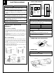
HOW TO CONNECT WIRING TO THE
TERMINALS
A. For solid core wiring
(1) Cut the wire end with a wire cutter or wire-cutting pliers, then strip
the insulation to about 25 mm (15/16") to expose the solid wire.
(2) Using a screwdriver, remove the terminal screw(s) on the terminal
board.
(3) Using pliers, bend the solid wire to form a loop suitable for the
terminal screw.
(4) Shape the loop wire properly, place it on the terminal board and
tighten securely with the terminal screw using a screwdriver.
B. For strand wiring
(1) Cut the wire end with a wire cutter or wire-cutting pliers, then strip
the insulation to about 10 mm (3/8") to expose the strand wiring.
(2) Using a screwdriver, remove the terminal screw(s) on the terminal
board.
(3) Using a round terminal fastener or pliers, securely clamp a round
terminal to each stripped wire end.
(4) Position the round terminal wire, and replace and tighten the
terminal screw using a screwdriver.
A. Solid wire
Strip 25 mm (15/16")
Insulation
Loop
B. Strand wire
Strip 10 mm (3/8")
Round
terminal
Wire
Screw with
special washer
Round terminal
Terminal
board
Wire
Screw with
special washer
Round
terminal
Terminal block
4
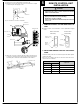
ELECTRICAL WIRING
1. CONNECTION DIAGRAMS
3. INDOOR UNIT
Indoor unit
Control box
Tapping screw
2. CONNECTION CORD PREPARATION
Power supply cord
or connection cord
CAUTION
Use care not to mistake the power supply cord and
connection wires when installing.
(1) Remove the two tapping screws and pull the control box downward.
30 mm (1-3/16")
40 mm or more
(1-9/16")
For earth
CAUTION
1 Be sure to refer the above diagram and do correct field
wiring.
Wrong wiring causes malfunction of the unit.
2 Check local electrical codes and also any specific
wiring instructions or limitation.
1
2
3
L
N
1
2
3
GG
1
2
3
INDOOR
INDOOR UNIT
OUTDOOR UNIT
TERMINAL
DISCON-
NECT
SWITCH
(FIELD
SUPPLY)
Grounding
line
14AWG
(Inter-unit)
Power lines
230/208 V
230/208 V
230/208 V
TERMINAL
Power supply line
Single-phase, 230/208 V
WARNING
Disconnect switch and circuit breaker for over current pro-
tection given in the table below is to be installed between
the indoor unit and the outdoor unit.
15A 240 V - 5A
Disconnect switch
Circuit breaker (or Fuse)
CIRCUIT
BREAKER
OR FUSE
(FIELD
SUPPLY)