
ABU36RSLX Installation Manual


1
INSTALLATION PROCEDURE
2
PREPARING INDOOR UNIT
INSTALLATION
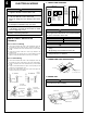
REMOVE THE INTAKE GRILLE AND SIDE COVER
(1) Remove the two Air filters.
(2) Remove the two Intake grilles.
• For 4 Left rear drain and 5 Left drain: Remove air filters and intake
grilles at three places. (Refer to “2 INDOOR UNIT INSTALLATION”.)
(3) Remove the Side cover A (Right side) and Side cover B (Right and
Left side).
• For 5 Left drain : Remove both the Side cover A (Right and Left
side). (Refer to “2 INDOOR UNIT INSTALLATION”.)
(4)
This air conditioner can be set up to intake fresh air. For information
about how to install for fresh-air intake, refer to “= FRESH-AIR INTAKE”.
INDOOR UNIT INSTALLATION
You can use the accessory template to help you install the indoor unit.
The template helps you determine the appropriate locations for suspen-
sion bolts and pipe opening (drain pipe and connection cord).
[For Half-Concealed Installation]
••
••
• Suspension-bolt pitch should be as shown in the figure.
2. SELECT PIPING DIRECTION
Select connection piping and drain piping directions.
[FOR 4 Left rear piping, 5 Left piping]
••
••
• Transfer the Drain cap and Drain cap seal.
Drain cap seal
Drain cap
Indoor unit
Drain pan
Drain cap seal
Drain cap
Push cap all the way on
(as far as it will go).
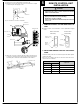
1. LOCATION OF CEILING SUSPENSION BOLTS
Suspension bolt pitch 1600 mm (63")
Dimensions
(Space Required
for Installation)
30 mm (1-3/16")
10 mm (3/8")
155 mm (6-3/32")
300 mm (12")
INDOOR UNIT (TOP VIEW)
INDOOR UNIT
Suspension bolt should
extend outward 30 to 75 mm.
(1-3/16" to 2-31/32")
30 mm (1-3/16")
3. DRILLING THE HOLES AND ATTACHING THE
SUSPENSION BOLTS
(1) Drill ø25 mm holes at the suspension-bolt locations.
(2) Install the bolts, then temporarily attach Special nuts A and B and a
normal M10 nut to each bolt. (The two special nuts are provided with
the unit. The M10 nut must be obtained locally.) Refer to the figure.
Bolt Strength 980 to 1470 N (100 to 150 kgf)
Ceiling panel
Special nut A (Included)
Special nut B (Included)
M10 Nut (Obtained locally)
10 to 15 mm
(13/32" to 19/32")
1 Right rear piping
5 Left piping
(Drain pipe only)
4 Left rear piping
(Drain pipe only)
2 Top piping
(Connection pipe only)
3 Right
piping
Cut off the piping outlet cutting groove
with a hacksaw, etc.
INDOOR UNIT (TOP VIEW)
Air filter
Intake grille
Tapping screw
INDOOR UNIT
Side cover A (Right side)
Side cover B
(Left side)
Side cover B (Right side)
Drilling position for Suspension bolt
Ceiling
Wall
Template
Drilling position for piping
Ceiling Opening: 1580 mm (62") 40 mm (1-9/16")
Ceiling panel
Ceiling Opening: 640 mm (25-3/16")
15 mm (19/32")
Suspension bolt should
extend outward 30 to 50 mm.
(1-3/16" to 1-31/32")
INDOOR UNIT
Ceiling panel
40 mm (1-9/16")