
ABU36RSLX Installation Manual


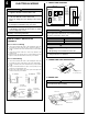

CONNECTION PIPE REQUIREMENT
ELECTRICAL REQUIREMENT
••
••
• Electric wire size:
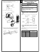
SELECTING THE MOUNTING POSITION
Decide the mounting position with the customer as follows:
CAUTION
Install heat insulation around both the gas and liquid pipes. Failure to do so may cause water leaks.
Use heat insulation with heat resistance above 248 °F. (Reverse cycle model only)
In addition, if the humidity level at the installation location of the refrigerant piping is expected to exceed 70%, install heat
insulation around the refrigerant piping. If the expected humidity level is 70-80%, use heat insulation that is 15 mm (19/32 in.) or
thicker and if the expected humidity exceeds 80%, use heat insulation that is 20 mm (3/4 in.) or thicker.
If heat insulation is used that is not as thick as specified, condensation may form on the surface of the insulation.
In addition, use heat insulation with heat conductivity of 0.045 W/(m·K) or less (at 68 °F).
••
••
• Use pipe with water-resistant heat insulation.
INDOOR UNIT
(1) Install the indoor unit level on a strong wall which is not subject to vibration.
(2) The inlet and outlet ports should not be obstructed : the air should be able to
blow all over the room.
(3) Do not install the unit where it will be exposed to direct sunlight.
(4) Install the unit where connection to the outdoor unit is easy.
(5) Install the unit where the drain pipe can be easily installed.
(6) Take servicing, etc., into consideration and leave the spaces shown in the
figure. Also install the unit where the filter can be removed.
WARNING
Select installation locations that can properly support the weight of the indoor and outdoor units. Install the units securely so
that they do not topple or fall.
CAUTION
1 Do not install where there is the danger of combustible gas leakage.
2 Do not install the unit near heat source of heat, steam, or flammable gas.
3 If children under 10 years old may approach the unit, take preventive measures so that they cannot reach the unit.
[FOR HALF CONCEALED INSTALLATION]
Diameter
Gas
15.88 mm (5/8 in.)
Liquid
9.52 mm (3/8 in.)
MIN.
1.0
Connection cord (mm )
MAX.
2.5
••
••
• Install all electrical works in accordance to the standard.
••
••
• Install the disconnect device with a contact gap of at least 3 mm (1/8") in all poles nearby the units. (Both indoor unit and outdoor unit)
••
••
• Install the circuit breaker nearby the units.
2
GENERAL
This INSTALLATION INSTRUCTION SHEET briefly outlines where and how to install the air conditioning system. Please read over the entire set of instructions
for the indoor and outdoor units and make sure all accessory parts listed are with the system before beginning.
Ceiling panel
Ceiling panel
INDOOR UNIT
80 mm (3-1/8")
or over
150 mm (6")
or over
10 mm (3/8")
or over
2,400 mm (94")
or more
Floor
Ceiling
INDOOR UNIT
80 mm (3-1/8")
or over
Ceiling
150 mm (6")
or over
10 mm (3/8")
or over
2,400 mm (94")
or more
Floor