
ABU36RSLX Installation Manual

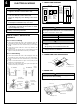


RED
WHITE
BLACK
REMOTE
CONTROL
POWER
SUPPLY
123123
••
••
• To use the optional wired remote control, set up the wiring as shown in
the diagram below.
••
••
• Use the clamps to fasten the remote control wire in three locations.
••
••
• Set up the wiring so that the remote control wire passes under the
capacitor and the plastic.
••
••
• Change the setting for the electrical circuits.
Switch 4 (SW4) on the printed circuit board inside the electric compo-
nent box must be set as follows.
Attach the remote control wire and cable clips.
Do not group the connection cord and remote control wire together.
RED
WHITE
REMOTE
CONTROL
BLACK
POWER
SUPPLY
231 231
Clamp
Remote control wire
Capacitor, Plastic
Clamp
Clamp
Control box
Terminal board
Cable clip
Cable clip
Connection cord
Remote control wire
Wires
SW4
SW4 SW4
Wireless remote
control type
Wired remote
control type
SU
MO
TU
WE
TH FR
SA
(1) Stop the air conditioner operation.
(2) Press the master control button and the fan control button simultane-
ously for 2 seconds or more to start the test run.
Unit number (usually 0)
Error code
(3) Press the start/stop button to stop the test run.
[SELF-DIAGNOSIS]
When the error indication “E:EE” is displayed, follow the following items to
perform the self-diagnosis. “E:EE” indicates an error has occurred.
REMOTE CONTROLLER DISPLAY
(1) Stop the air conditioner operation.
(2) Press the set temperature buttons
simultaneously for
5 seconds or more to start the self-diagnosis.
Refer to the following tables for the description of each error code.
Test run display
(3) Press the set temperature buttons simultaneously for
5 seconds or more to stop the self-diagnosis.
Ex. Self-diagnosis
Error code Error contents
Communication error
(indoor unit
remote controller)
Communication error
(indoor unit outdoor unit)
Room temperature sensor open
Room temperature sensor short-circuited
Indoor heat exchanger temperature sensor open
Indoor heat exchanger temperature sensor short-
circuited
Outdoor heat exchanger temperature sensor
Power source connection error
Float switch operated
Outdoor temperature sensor
Discharge pipe temperature sensor
Model abnormal
Indoor fan abnormal
00
01
02
03
04
05
06
08
09
0A
0c
11
12
TEST RUN