
ABU36RSLX Installation Manual


5
REMOTE CONTROL UNIT
INSTALLATION
1. REMOTE CONTROL UNIT HOLDER INSTALLA-
TION
••
••
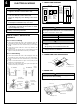
• Install the remote control unit holder to a wall or pillar with the tapping
screws.
Remote Control Unit
holder fixing
Remote Control
Unit mounting
Remote control
unit holder
Tapping
screws
(small)
1 Set
2 Push
Remote
control unit
2. SWITCHING REMOTE CONTROL UNIT SIGNAL
CODE
• Remote control unit settings
(1) Press the START/STOP button and display only the clock.
(2) Press the MASTER CONTROL button continuously for more than five
seconds to display the current signal code.
(3) Change the signal code with the
button ( ).
(4) Press the MASTER CONTROL button again to return to the clock
display and change the signal code.
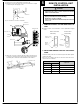
JM1
JM2
JM3
Indoor unit
Printed circuit board
Jumper wire
JM3
Connect
Disconnect
Connect
Disconnect
Remote control unit
signal code
A (Primary setting)
B
C
D
JM2
Connect
Connect
Disconnect
Disconnect
Confirm the setting of the remote control unit signal code and the printed
circuit board setting.
If these are not confirmed, the remote control unit cannot be used to
operate for the air conditioner.
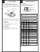
CAUTION
1 Check that the indoor unit correctly receives the
signal from the remote control unit, then install the
remote control unit holder.
2 Select the remote control unit holder selection site by
paying careful attention to the following:
Avoid places in direct sunlight.
Select a place that will not be affected by the heat from
a stove, etc.