
ABU36RSLX Installation Manual


POWER
SUPPLY
REMOTE
CONTROL
321
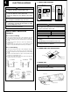
(2) Remove the Cover A and install the Connection cord.
(3) Reattach Cover A. Then fasten the control box back into its original
position using the two tapping screws.
Cover A
Control box
5
REMOTE CONTROL UNIT
INSTALLATION
1. REMOTE CONTROL UNIT HOLDER INSTALLA-
TION
••
••
• Install the remote control unit holder to a wall or pillar with the tapping
screws.
Remote Control Unit
holder fixing
Remote Control
Unit mounting
Remote control
unit holder
Tapping
screws
(small)
1 Set
2 Push
Remote
control unit
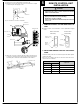
2. SWITCHING REMOTE CONTROL UNIT SIGNAL
CODE
Jumper wire
JM3
Connect
Disconnect
Connect
Disconnect
Remote control unit
signal code
A (Primary setting)
B
C
D
JM2
Connect
Connect
Disconnect
Disconnect
Control box
Terminal board
Connection cord
Confirm the setting of the remote control unit signal code and the printed
circuit board setting.
If these are not confirmed, the remote control unit cannot be used to
operate for the air conditioner.
(5) Attach the connection cord and cable clips. Make sure that they are
positioned so that they will not interfere with opening and closing of
the intake grille or with removal and installation of the air filters.
CAUTION
1 Check that the indoor unit correctly receives the
signal from the remote control unit, then install the
remote control unit holder.
2 Select the remote control unit holder selection site by
paying careful attention to the following:
Avoid places in direct sunlight.
Select a place that will not be affected by the heat from
a stove, etc.
(4) Use lock nuts to secure the conduit tube.
Cable clip
Connection cord
Conduit
Lock nut
Earth screw