Introduction This Operating Manual tells you how to put your PC into operation and how to operate it in daily use. It applies for all configuration levels. Depending on the configuration level chosen some of the hardware components described may not be available on your PC. Please observe the notes on your operating system. Your SCENIC Edition Mi is a powerful PC which is suitable for both professional and private use.
Introduction Notational conventions Notational conventions The meanings of the symbols and fonts used in this manual are as follows: ! i ² Pay particular attention to texts marked with this symbol. Failure to observe this warning endangers your life, destroys the system, or may lead to loss of data. This symbol is followed by supplementary information, remarks and tips. Texts which follow this symbol describe activities that must be performed in the order shown.
Important notes In this chapter you will find information regarding safety which it is essential to take note of when working with your PC. The manufacturer's notes contain helpful information on your PC. Safety ! • • • • • • • • Pay attention to the information provided in the manual "Safety and Ergonomics".
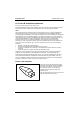
Important notes Manufacturer's notes Notes on installing and removing boards Boards with electrostatic sensitive devices (ESD) may be identified by labels. When you handle boards fitted with ESDs, you must observe the following points under all circumstances: • • • • • You must always discharge yourself (e.g. by touching a grounded object) before working. The equipment and tools you use must be free of static charges. Pull out the power plug before inserting or pulling out boards containing ESDs.
Manufacturer's notes Important notes Disposal and recycling This device has been manufactured to the greatest possible degree from materials which can be recycled or disposed of in a manner that is not environmentally damaging. The device is taken back after use, so that it can be recycled, provided that it is returned in a condition which is the result of normal use. Any components not recuperated will be disposed of in an environmentally acceptable manner.
Important notes Manufacturer's notes FCC Class B Compliance Statement If there is an FCC statement on the device, then: The following statement applies to the products covered in this manual, unless otherwise specified herein. The statement for other products will appear in the accompanying documentation.
Manufacturer's notes Important notes For the United States and Canada Use a UL listed and CSA labeled cord set consisting of a three conductor cord with a maximum length of 15 feet. For units which stand on a desk or table, type SVT or SJT cord sets shall be used. For units which stand on floor, only SJT type cord sets shall be used. The cord set must be selected according to the current rating for your unit.
Important notes Transporting the PC For the United Kingdom Should the plug on the flexible cord not be of the type for your socket outlets, do not use an adapter but remove the plug from the cord and discard. Carefully prepare the end of the supply cord and fit a suitable plug.
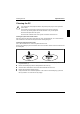
Cleaning the PC Important notes Cleaning the PC ! Turn off all power and equipment switches and pull the power plug out of the grounded power outlets. Do not clean any interior parts yourself, leave this job to a service technician. Do not use any cleaning agents that contain abrasives or may corrode plastic. Ensure that no liquid enters the system. Ensure that the ventilation areas of the system unit and the monitor are free.
Preparation for use and operation ! Please take note of the safety information in the chapter "Important notes". Unpacking and checking the delivery It is recommended not to throw away the original packaging material! It may be required for reshipment at some later date. ² ² ² ² Unpack all the individual parts. Check the delivery for damage incurred during transport. Check whether the delivery agrees with the details in the delivery note.
Preparation for use and operation Setting up the PC Setting up the PC ! When installing your PC, give consideration to the recommendations on video workstation ergonomics in the manual "Safety and Ergonomics". Set up the PC only in its correct orientation. The points to observe are illustrated on the following pages. We recommend that you place your equipment on a surface with good anti-slip qualities.
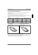
Connecting devices Preparation for use and operation Ports for external devices The ports for external devices are on the rear of the system unit. The ports available on your PC depend on the configuration level you have selected. The standard ports are marked with symbols like those below or similar symbols. Exact details of the position of the ports are supplied in the Technical Manuals for the boards.
Preparation for use and operation Connecting devices Connecting the mouse ² Plug the connector of the mouse cable into the mouse port. i If you attach a serial mouse, you can disable the mouse controller in the BIOS-Setup in order to free the IRQ12 for a different application. If the mouse controller is disabled, you will not be able to operate a mouse connected to the PS/2 mouse port. Connecting the keyboard i Use only the keyboard cable supplied.
Connecting the PC to the line voltage Preparation for use and operation Connecting the PC to the line voltage 100 V - 125 V 200 V - 240 V ² Check the rated voltage. ! 115 = 100 V to 125 V 230 = 200 V to 240 V If the rated voltage does not agree with the local line voltage, you must move the wiper switch to the correct position. 2 1 ² Plug the system unit's power cable into the system unit (1) and then into the grounded power outlet (2).
Preparation for use and operation Indicators and switches Indicators and switches 3 1 4 2 5 1 = CD-ROM indicator 2 = Floppy disk indicator 3 = Hard disk indicator 4 = Power-on indicator 5 = ON/OFF switch 1 - CD-ROM indicator The indicator lights up when the CD-ROM drive of the system unit is accessed. You may only remove the CD when the indicator is dark. 2 - Floppy disk indicator The indicator lights up when the floppy disk drive of the system unit is accessed.
Indicators and switches Preparation for use and operation Switching on the PC for the first time When you switch on your PC for the first time the supplied software is set up and configured. ² ² Switch your monitor on. Switch the system unit on with the ON/OFF switch. The power-on indicator lights green and the PC is started. ² Adjust the brightness if necessary (see the Operating Manual for the monitor).
Preparation for use and operation Indicators and switches Switching on the PC ! ² ² If after switching on the PC you see nothing but flickering stripes on the screen, switch the PC off immediately (see "Troubleshooting and tips" - "Flickering or drifting stripes on the monitor screen"). Switch the monitor on (see the Operating Manual for the monitor). Switch the system unit on with the ON/OFF switch. The power-on indicator lights green and the PC is started.
Working with floppy disks Preparation for use and operation Working with floppy disks ! Follow the instructions supplied by the vendor of the floppy disks. Never clean the floppy disk drives with cleaning disks. Even just one attempt would destroy the read/write head in the disk drive within 20 seconds.
Preparation for use and operation Keyboard Keyboard 1 2 1 = function keys 2 = alphanumeric keypad 3 4 3 = cursor control keys 4 = numeric keypad (calculator keypad) Important keys and key combinations The following description of keys and key combinations refers to MS Windows. Details of other keys and key combinations can be found in the documentation of the relevant application program. Enter key confirms or starts the marked selection.
Settings in BIOS Setup Num Ctrl Ctrl Preparation for use and operation Num Lock key by pressing the Num Lock key you switch between the upper- and lower-case levels of the calculator keypad. At upper-case level (Num Lock indicator lit) the digit and comma keys are active. At lower-case level (Num Lock indicator not lit) the cursor control functions are active in the calculator keypad. Ctrl key starts key combination actions. Alt Del Warm boot restarts your PC.
Troubleshooting and tips ! Take note of the safety hints in the manual "Safety and Ergonomics" and in the chapter "Preparation for use and operation", when you connect or disconnect cables. If a fault occurs, try to correct it as described: • in this chapter • in the documentation of the connected devices • in the help systems of the software used. If you fail to correct the problem, proceed as follows: ² ² ² Switch the PC off. Make a note of the steps and the circumstances that led to the fault.
Troubleshooting and tips The screen stays blank If your screen remains blank this may have the following causes: Monitor is switched off ² Switch your monitor on. Screen has been blanked ² Press any key on the keyboard. or ² Deactivate screen blanking (screen saver). Enter the appropriate password. Brightness control is set to dark ² Set the brightness control to light. For detailed information, please refer to the Operating Manual supplied with your monitor.
Troubleshooting and tips Flickering or drifting stripes on the monitor screen ! Switch off the PC immediately! The flickering stripes are caused either by an old-type screen that does not support the horizontal frequency of 47 kHz, or by an incorrect monitor selection under MS-Windows. The drifting screen display is caused when the selected frequency and/or resolution is wrong. The default screen values are 800x600 pixels at 75 Hz and for 64K colors.
Troubleshooting and tips Time and/or date is not correct ² Set the time and/or date. You can set the time and date in the BIOS Setup or in the operating system. i If the time and date are repeatedly wrong when you switch on your PC, the battery is flat. Change the lithium battery as described in the Chapter "Memory, processor, lithium battery".
Troubleshooting and tips Tips The PC cannot be switched off with the ON/OFF switch Cause: The PC has not been switched on with the ON/OFF switch. ² Press the ON/OFF switch again. Cause: System crash ² Press the ON/OFF switch for at least four seconds, until the device switches off. Out of system resources If you have too many applications running at once, you may experience problems due to a lack of system resources.
System expansions It may be necessary to update the BIOS when carrying out a system expansion or hardware upgrade. In this instance, please contact our service. ! This chapter describes all the activities required to modify your PC hardware (e.g. installing boards or drives). Memory and processor upgrading are described in the Technical Manual for the system board. Read the supplied documentation before installing new drives and/or boards.
System expansions Assembling the system unit ² Place the housing on the system unit (1) from above so that the distance (a) is approx. 10 mm. While doing so, make sure that the housing is hooked into the system unit at the bottom. ² Push the casing in the direction of the arrow (2). ² ² Fasten the screws (3). ² If you have disconnected cables, reconnect them at the rear. 1 2 a 3 Return the system unit to its original position.
System expansions Installing an accessible drive ² Open the system unit (see "Opening the system unit"). 1 2 ² ² Lever out the plastic drive cover off the casing (1). Pull the metal cover forward (2). If you remove the drive again later, you will have to reinstall the covers. ! ² Make the required settings on the drive (if necessary, on installed drives as well). 2 2 1 3 ² ² ² Slide the drive into the system unit (1). Fasten the drive with the screws (2).
System expansions ² Close the system unit (see "Assembling the system unit"). If necessary, you must adapt the entry for the drive in the Setup menu. Replacing the hard disk or floppy disk drive ² Open the system unit (see "Opening the system unit"). Removing the drive carrier 1 3 2 ² ² ² 32 Press the unlocking device in the direction of the arrow (1). Swivel the drive carrier in direction of the arrow (2). Remove the drive carrier in direction of the arrow (3).
System expansions Replacing a hard disk drive 1 1 2 ² ² ² ² Remove the four screws (1). Pull the hard disk drive out of the carrier (2). Take the new hard disk drive out of its packaging. Make the required settings (e.g. master-slave settings) on the drive. 2 2 1 ² ² ² ² Slide the hard disk drive into the drive carrier (1). Fasten the hard disk drive with the screws (2). Plug the data and the power supply connectors into the hard disk drive. Close the system unit (see "Assembling the system unit").
System expansions Changing the floppy disk drive 2 1 1 ² ² ² Remove the four screws (1). Pull the floppy disk drive out of the carrier (2). Take the new floppy disk drive out of its packaging. 1 2 2 ² ² ² ² Slide the floppy disk drive into the drive carrier (1). Fasten the hard disk drive with the screws (2). Plug the data and the power supply connectors into the hard disk drive. Close the system unit (see "Assembling the system unit").
System expansions Installing the hard disk carrier 1 2 ² ² Slide the drive carrier in direction of the arrow (1). Swivel the drive carrier in direction of the arrow (2). Please ensure that the guide rail is in the groove. ² Close the system unit (see "Assembling the system unit"). i If necessary, you must adapt the entry for the drive in the Setup menu.
System expansions Installing a board Observe the notes on installing and removing boards in the chapter "Important notes". ! Old ISA boards which require a 5 V power supply are not supported. You can install boards which are up to 300 mm long. The number, position and arrangement of the board slots on system board can be found in the technical manual for the system board. Boards may be installed when the device is shipped. 4 3 1 ² ² Remove the screw (1).
System expansions Settings in BIOS Setup If you have installed or removed a PCI board, please check in the BIOS Setup the settings for the relevant PCI slot. If necessary, change the settings. Further information is provided in the documentation for the PCI board. Memory, processor, lithium battery Details of how and if you can upgrade the main memory or retrofit the second-level cache of your PC are provided in the Technical Manual for the system board.
Technical data Electrical data Regulations complied with: EN 60950 / VDE 0805 UL 1950 CSA 22.2 No.950 Protection class: I Rated voltage range: (selectable) 100 V to 125 V / 200 V to 240 V Frequency: 50 Hz - 60 Hz Max. rated current: 100 V - 125 V / 2.0 A 200 V - 240 V / 1.
Technical data Interrupt table Interrupt table Please note that an interrupt cannot be used by two applications at the same time.
Index ! i 2 ² 2 2 A Accessible drive installing 31 Accumulator, disposal 5 Activating, security measures 21 Address 40 Alphanumeric keypad 20 Alt Gr key 20 Assembling, PC 30 Assignment DMA channels 40 I/O address 40 interrupt 40 Audio input 13 Audio output 13 B Battery 37 disposal 5 replacing 37 BIOS Setup 21 security functions 21 Board installing 36 safety 4 C Cable connecting 12 disconnecting 12 Cabling, PC 12 Cache installing 37 Calculator keypad 20 CD, Windows 26 CD-ROM drive indicator 16 installi
Index Class B Compliance Statement 6 Cleaning 9 Clearance 39 Closing the casing 30 Configuration, BIOS-Setup 21 Connecting cables 12 devices 12 keyboard 14 monitor 14 mouse 14 parallel port 14 power voltage 15 serial port 14 to power voltage 15 Contents of delivery 11 Control key 21 Ctrl key 21 Ctrl+Alt+Del 21 Cursor control keys 20 D Dark screen 24 Data protection 21 technical 39 Date, not correct 26 Devices connecting 12 interface 13 Dimensions 39 Diskette 19 cannot be read or written 25 write-protection
Index system unit 23 time 26 Error message 26 ESD 4 Euro key 20 Expansion 29 External devices connecting 12 ports 13 F FCC statement 6 Floppy disk drive changing 32 indicator 16 Function keys 20 G Game port 13 Green, power-on indicator 16 Guarantee coupon booklet 11 H Hard disk defect 26 indicator 16 Hard disk drive replacing 32 I I/O address 40 IDE drives 30 Important notes 3 Indicator power-on indicator 16 power-on indicator fails to light 23 Installing accessible drive 31 board 36 new Software 23 Insuff
Index L LAN-port 13 Line in 13 Line out 13 Lithium battery 37 replacing 37 M Main memory 37 Manufacturer’s notes 4 Memory, upgrading 37 Menu key 20 Microphone jack 13 Monitor connecting 14 transporting 8 Monitor port 13 Mouse cleaning 9 connecting 14 error 25 Mouse port 13 N New Installation, Software 23 No screen display 24, 25 Not enough memory 27 Notational conventions 2 Note board 4 CE certificat 5 disposal 5 energy saving 4 important 3 manufacturer 4 power cord selecction 6 safety 3 Num Lock key 21 Nu
Index connecting devices 14 PC cabling 12 cannot boot 23 cleaning 9 closing 30 connecting 12 connecting to power voltage 15 opening 29 ports 13 setting up 12 switching off 16, 18 switching on 16, 18 transporting 8 Ports, external devices 13 Power cord selecction 6 Power management 27 Power-on indicator 16 dark 23 POWERSAV.
Index rated voltage 15 Settings BIOS Setup 21, 37 Setup, see BIOS Setup Shift key 20 Software, New Installation 23 SSLAUNCH 4 Start key 20 Streamer, installing 31 Summer time 26 Surface 39 Switching off, PC 16, 18 Switching on, PC 16, 18 Symbols, explanation of 2 System expansion 29 System settings, BIOS Setup 21 System unit, see PC T Technical data 39 Time, not correct 26 Tips 23, 27 Transport 8 Trouble floppy 25 mouse 25 screen 24, 25 system unit 23 Troubleshooting 23 U Unpacking 11 Upgrading memory 37 p
Contents Introduction......................................................................................................................................1 Notational conventions ......................................................................................................................2 Important notes................................................................................................................................3 Safety ............................................................
Contents System expansions....................................................................................................................... 29 Opening the system unit.................................................................................................................. 29 Assembling the system unit............................................................................................................. 30 Installing and removing drives ...................................................
A26361-K515-Z100-1-7619
A26361-K515-Z100-1-7619 SCENIC Edition Mi Operating Manual August 1998 edition Microsoft, MS, MS-DOS, Windows and Windows NT are Trademarks of Microsoft Corporation. VESA and DPMS are trademarks of Video Electronics Standards Association. PS/2 is a registered trademark of International Business Machines, Inc. Pentium is a registered trademark of Intel Corporation, USA.