
Operating Manual
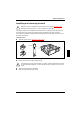
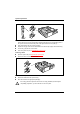
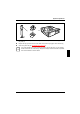
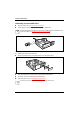
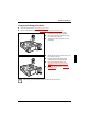
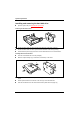
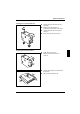
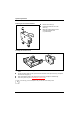
Table Of Contents
- Title
- Contents
- Introduction
- Important notes
- Preparation for use and operation
- Unpacking and checking the delivery
- Preparing the PC for use
- Setting up the PC
- Connecting devices
- Connecting the PC to the line voltage
- Unlocking/locking the system unit
- Switching the PC on and off
- Indicators on the system unit
- Keyboard
- Working with floppy disks
- Settings in BIOS Setup
- Property and data protection
- Troubleshooting and tips
- System expansions
- Technical data
- Index

System expansions
A26361-K520-Z100-1-7619
31
Installing and removing a board
!
Observe the notes on installing and removing boards in the chapter "Important notes".
Old ISA boards which require a -5 V power supply are not supported.
The number, position and constellation of the board slots on the system board can be found in the
technical manual for the system board. Boards may be installed when the device is shipped.
Any angled slot is intended for high PCI boards including connectors and cables. However, you can
also install an ISA board.
Installing a board
Open the system unit (see "Opening the system unit").
3
1
2
Press on the clip in the direction of the arrow (1) and remove it (2).
Remove the rear slot cover plate from the slot (3).
!
Do not dispose of the rear slot cover plate. For cooling, protection against fire and in order
to comply with EMC regulations, you must refit the rear slot cover plate if you remove the
board.
Take the new board out of its packaging.
Make the required settings for the board.