Connectivity Peripherals Installation Guide Point 510 Point 1600
Connectivity Peripherals Installation Guide Point 510 Point 1600
Fujitsu Personal Systems, Inc. has made every effort to ensure the accuracy and completeness of this document. However, because ongoing development efforts are continually improving our products, we cannot guarantee the accuracy of the contents of this document. We disclaim liability for errors, omissions, or future changes herein. Point 510 and Point 1600 are trademarks of Fujitsu Personal Systems, Inc. The Fujitsu logo is a registered trademark of Fujitsu Ltd.
Agency Compliance FCC Notice This equipment has been tested and found to comply with the limits for a Class B digital device, pursuant to Part 15 of the FCC rules. These limits are designed to provide reasonable protection against harmful interference in a residential installation. This equipment generates, uses, and can radiate radio frequency energy and, if not installed and used in accordance with the instructions, may cause harmful interference to radio communications.
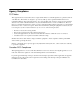
Table of Contents About This Guide .............................................................................................................................. vii Organization....................................................................................................................................................... vii Chapter 1 Introduction to Connectivity Peripherals ....................................................................................... 1-1 Cradle Module ..............
vi
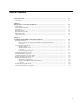
About This Guide This guide provides installation instructions for connectivity peripherals compatible with Point 1600 and Point 510 pen tablet systems including the following: • • • • • • Portable port expander Port replicator* High-connectivity cradle* High-usage cradle* Wall-mount cradle* Charge-only cradle * These connectivity peripherals are available in locking and non-locking versions. Information given in this manual applies to both versions.
viii About This Guide
Chapter 1 Introduction to Connectivity Peripherals Connectivity peripherals for the Point 510 and Point 1600 pen tablet systems are engineered using modular design principles. Each connectivity peripheral is assembled using components which may be used in different connectivity peripheral products. Components that make up connectivity peripherals are shipped unassembled. This chapter gives an introduction to each connectivity peripheral.
Table 1-2 shows what type of connectors are present on each connectivity peripheral product. ✔ ✔ ✔ Serial Port B ✔ ✔ ✔ Mouse Port† (on portable port expander) ✔ ✔ ✔ Keyboard ✔ ✔ ✔ Mouse Port (on cradle module) ✔ ✔ ✔ Parallel Port ✔ ✔ ✔ Floppy Drive Port ✔ ✔ ✔ Video Port ✔ ✔ ✔ DC Power Input ✔ ✔ ✔ Charge-Only Cradle Serial Port A Wall-Mount Cradle* Port Replicator High-Connectivity Cradle Portable Port Expander High-Usage Cradle Table 1-2.
Cradle Module 1 The cradle module is a central component in the following connectivity peripherals: • • • • port replicator high-usage cradle high-connectivity cradle wall-mount cradle The cradle module holds the pen tablet when it is inserted in these connectivity peripherals. Two types of cradle modules are available, a locking version (cradle module FMW26CR8), and a non-locking version (cradle module FMW26CR28).
Port Replicator 1 The port replicator provides the combined features of the portable port expander, plus additional keyboard and power connectors. The port replicator is assembled by installing the portable port expander in the cradle module. For assembly instructions, see “Assembling the Port Replicator” in Chapter 2 of this manual. Assembled Package Components + = Cradle Module Port Replicator Portable Port Expander (Note: Latch and spacer must be removed before assembly.
High-Connectivity Cradle 1 The high-connectivity cradle provides all the connectivity of the port replicator and is designed for desk-top or counter-top installations where the cradle remains stationary. Locking versions are equipped with a tubular lock which allows you to lock the pen tablet into the cradle. The high-connectivity cradle is assembled using a cradle module, cradle base, and portable port expander.
Wall-Mount Cradle 1 The wall-mount cradle provides a folding keyboard tray and can be located in hallways or other wall areas to give mobile workers a convenient place to store the pen tablet, input data with a keyboard and connect the pen tablet to an external power source. Locking versions are equipped with a tubular lock which allows you to lock the pen tablet into the cradle. The wall-mount cradle is assembled using a cradle module, wall-mount base, and a keyboard.
Chapter 2 Assembling and Installing Connectivity Peripherals This chapter describes the assembly and installation of connectivity peripherals. Portable Port Expander 2 The portable port expander can be used alone with the pen tablet or it can be installed in the cradle module as a component in other connectivity peripheral assemblies. The portable port expander is equipped with a latch mechanism and spacer to allow it to be attached directly to the pen tablet.
Connectors 2 Figure 2-2 shows the location of peripheral connectors on the portable port expander. Mouse Port Serial Port B Serial Port A Parallel Port Floppy Disk Drive Port Video Port Figure 2-2. Bottom View, Portable Port Expander Peripheral connectors on the portable port expander are described in Table 2-1. Table 2-1.
Assembling the Port Replicator 2 The port replicator is assembled using a cradle module and a portable port expander. The process of assembling the port replicator is outlined in the following: • Install the portable port expander in the cradle module. • Attach the rubber feet to the cradle module. • Attach the wire catch to the cradle module. (Required if using the port replicator with the folding desk stand.) Detailed procedures for these tasks are given in this section.
To install the portable port expander in the cradle module, 1. Insert the portable port expander through the bottom of the cradle module as shown in Figure 2-3. 2. Position the portable port expander so you can see the portable port expander screw holes through the two holes inside the cradle module. 3. Insert the two screws (provided with the portable port expander) as shown in Figure 2-3 and tighten until snug. Screws Cradle Module Tubular Lock Portable Port Expander Figure 2-3.
replicator on the desk stand in one of three orientations: one landscape-mode and two portrait-mode positions. Wire Catch Feet Feet Attach wire catch here for portrait orientation (left side up). Attach wire catch here for portrait orientation (right side up). Figure 2-4. Port Replicator (Back View) To install the wire catch, 1. Determine which set of mounting holes is appropriate depending on how you intend to orient the pen tablet on the desk stand.
DC Power Input Port Mouse Port (on cradle module) Mouse Port (on portable port expander) Serial Port B Serial Port A Keyboard Port Parallel Port Video Port Floppy Disk Drive Port Figure 2-5. Bottom View, Port Replicator Connectors on the port replicator are described in Table 2-2. Table 2-2. Port Replicator Connectors Port Description Serial Port A This connector can be used to connect an external device with a serial interface such as a modem. This is a fully-functional RS232-C serial port.
Using the Folding Desk Stand 2 The FMWDS3 folding desk stand is recommended for use with the port replicator. The desk stand can be locked into place in five positions, one folded position and four open positions. The four open positions allow you to set up the desk stand in four different viewing angles. A storage pouch is provided with the desk stand. Hook wire catch over this part of desk stand. Top of desk stand snaps over rubber feet when stand is folded.
Assembling the High-Usage Cradle 2 The following outlines the process of assembling the high-usage cradle: • Attach the cradle module to the cradle base. • Install the AC adapter in the cradle base. Detailed procedures for assembling the cradle module, cradle base, and AC adapter are given in this section. (Peripherals, such as the keyboard and mouse, are attached later when the cradle is installed at the work site.
Cover Label Cradle Module Kensington Security Standard Slot Adjustment Knob Nylon Washer Star Washer Spacer Screw Cover Cradle Base Figure 2-7. High-Usage Cradle Assembly 3. Determine which side the adjustment knob will be installed on. The knob can be installed on either the right or left side of the cradle module to accommodate right- or left-handed users. 4.
To install the AC adapter in the cradle base, 1. Turn the cradle base upside down. 2. Detach one end of the Velcro strap and insert the AC adapter into the cavity in the bottom of the cradle base as shown in Figure 2-8. 3. Reattach the velcro strap to secure the AC adapter. 4. Attach the DC power cable from the AC adapter to the DC input connector on the cradle module. 5.
The location of peripheral connectors on the high-usage cradle are shown in Figure 2-8. Table 2-3 describes these connectors. Table 2-3. High-Usage Cradle Connectors Port Description Mouse Port This 6-pin mini-DIN plug is used to attach a PS/2-style mouse. DC Input This connector is used to connect a DC power source such as the Fujitsu AC adapter or auto adapter. Keyboard Port This 6-pin mini-DIN plug can be used to attach a PS/2-style keyboard.
Installing the High-Usage Cradle 2 To install the high-usage cradle at the work site, 1. Determine the appropriate desktop location. Account for: • Distance to an AC outlet. • Distance from desk edge to allow for easy access and positioning of a keyboard and mouse pad. • Desk or table legs so it is easy to sit in front of and use the system. • Routing the AC adapter power cord over the back edge of the desk, a notch in the desktop, or through a hole drilled in the desktop.
8. As an optional step, you can secure the cradle at the work site using one or both of the following methods: • Secure the cradle using a Kensington lock. The cradle base provides a Kensington Security Standard slot, called out in Figure 2-7, which is designed for use with Kensington locking devices such as the Kensington MicroSaver security system. Contact a Kensington dealer to obtain an appropriate security product.
Assembling the High-Connectivity Cradle 2 The following list outlines the process of assembling the high-connectivity cradle. Detailed procedures are given later in this section. • Install the portable port expander in the cradle module. To do so, follow the procedure given in “Assembling the Port Replicator” on page 2-3 before performing the following procedures. Do not, however, attach the feet or wire catch to the cradle module. • Attach the cradle module to the cradle base.
Screws Cradle Module Portable Port Expander Kensington Security Standard Slot Knob Nylon Washer Star Washer Spacer Screw Cradle Base Cover 545HUCAS Figure 2-10.
To install the AC adapter in the cradle base, 1. Turn the cradle base upside down. 2. Detach one end of the Velcro strap and insert the AC adapter into the cavity in the bottom of the cradle base as shown in Figure 2-11. 3. Reattach the velcro strap to secure the AC adapter. 4. Attach the DC power cable from the AC adapter to the DC input connector on the cradle module. 5.
Installing the High-Connectivity Cradle 2 To install the high-connectivity cradle, 1. Determine the appropriate desktop location. Account for: • Distance to an AC outlet. • Distance from desk edge to allow for easy access and positioning of a keyboard and mouse pad. • Desk or table legs so it is easy to sit in front of and use the system. • Routing the AC adapter power cord over the back edge of the desk, a notch in the desktop, or through a hole drilled in the desktop.
utilize these ports is determined by BIOS settings. Ensure that BIOS options are properly configured for the ports that you intend to use. Table 2-4. High-Connectivity Cradle Connectors Port Description Serial Port A This connector can be used to connect an external device with a serial interface such as a modem. This is a fully-functional RS232-C serial port. Serial Port B This connector can be used to connect an external device with a serial interface.
Installing the Wall-Mount Cradle 2 The wall-mount cradle is assembled during installation. Installing the wall-mount cradle involves the following general tasks: • Prepare the installation site for the wall-mount cradle. • Assemble and install the wall-mount cradle at the site. Procedures for these tasks are given in the following sections. Required Tools and Hardware 2 The following tools and hardware are required to install the wall-mount cradle.
To prepare the installation site for the wall-mount cradle, 1. Determine the appropriate location for the wall-mount cradle. Account for the following factors when selecting the location: • The wall-mount cradle protrudes from the wall about 3.5 inches with the keyboard tray in the closed position and about 10 inches with the keyboard tray in the open position. Ensure that the location you choose is compliant with local building codes and does not obstruct other activities in the work area.
Mounting Holes (To attach plate to wall.) Mounting Holes (To attach plate to wall.) Mounting Holes (To attach plate to junction box.) Mounting Holes (To attach plate to junction box.) Figure 2-12. Wall-Mount Cradle Mounting Plate To install the wall-mount cradle, 1. Attach the mounting plate to the junction box. To do so, align the square hole in the mounting plate with the junction box and fasten the plate to the junction box.
4. Connect the AC adapter’s AC power cable to the AC supply wire in the junction box. To do so, cut the wall plug off of the AC adapter’s AC power cable and discard the wall plug. Trim the end of the cable that connects to the AC adapter to a length of about 2’ and connect the cable wires directly to the AC supply wires in the junction box. Use twist-on wire connectors or other approved connectors in compliance with electrical codes. Warning Shut off power before working on a circuit.
7. Route the keyboard cable through the notch on the left side of the keyboard tray assembly as shown in Figure 2-15. 8. Connect the keyboard cable to keyboard port on the cradle module. Ensure that you have connected the keyboard cable to the correct port. The keyboard port is the middle connector on the bottom of the cradle module (closest to the DC input connector). 9.
11. Connect the AC power cable (from the junction box) to the AC adapter. To do so, bring the keyboard tray assembly close to the cradle plate that is already mounted on the wall. 12. Attach the keyboard tray assembly to the mounting plate as shown in Figure 2-16, Figure 2-17, and Figure 2-18. Use the six screws (size # 8) provided with the wall-mount cradle. (Figure 2-15 on page 2-23 also shows the location of these screws.
Push Tighten Figure 2-17. Attaching Keyboard Tray Assembly to Mounting Plate (Left Side) Tighten Figure 2-18. Attaching Keyboard Tray Assembly to Mounting Plate (Bottom) 13. Fasten the cradle module to the mounting plate using the two (size #6) screws provided with the wall-mount cradle, shown in Figure 2-15 on page 2-23. To ensure proper alignment of the cradle module, push the cradle module toward the wall while you tighten the screws.
14. Tighten the two (size #10) screws, one on each side, that you installed in step 9 to fasten the cradle module to the keyboard tray assembly. To ensure proper alignment, push the cradle module toward the wall as shown in Figure 2-19 and Figure 2-20 while you tighten the screws. Tighten Push Figure 2-19. Fastening Cradle Module (Left Side) Tighten Push Figure 2-20.
15. Apply the cover label provided with the cradle module to the inside of the cradle module as shown in Figure 2-15 on page 2-23. (This label covers access holes in the cradle module that are not used in this assembly.) 16. Ensure that the cradle module is properly aligned as shown in Figure 2-21. There should be no gap between the cradle module and the mounting plate. No Gap No Gap Figure 2-21.
Testing the Wall-Mount Cradle After Installation 2 The wall-mount cradle should be tested after it is installed. To do so, perform the following procedure and correct any problems noted. 1. Turn on AC power to the junction box. 2. Insert a pen tablet into the cradle module. 3. Confirm that external power is supplied to the pen tablet (via the AC adapter).
Connectors 2 Connectors on the wall-mount cradle are described in Table 2-5. Table 2-5. Wall-Mount Cradle Connectors Port Description DC Input This connector is used to connect a DC power source such as the Fujitsu AC adapter or auto adapter. Keyboard Port This 6-pin mini-DIN plug can be used to attach a PS/2-style keyboard. Mouse Port* This connector can be used to connect a PS/2-style mouse.
Installing the Charge-Only Cradle 2 To install the charge-only cradle, 1. Place the cradle in the location where it will be used. 2. Plug the DC power cable from AC adapter into the DC input connector located on the bottom of the charge-only cradle. 3. Plug the AC power cable into the AC adapter and into an AC outlet. The charge-only cradle is ready to be used. DC Power Input Connector Figure 2-23.
Confirming External Power Is Supplied 2 All connectivity peripherals (except for the portable port expander) supply power to the pen tablet when the AC adapter is properly connected. To confirm that external power is supplied, place the pen tablet in the connectivity peripheral and observe the Charge Status light on the pen tablet.
2-32 Assembling and Installing Connectivity Peripherals
Index C charge-only cradle description, 1-6 installing, 2-30 connectivity peripherals compatible pen tablets, vii connectors, table, 1-2 locking and non-locking versions, vii cradle module, 1-3 using with folding desk stand, 2-4, 2-7 wire catch, attaching, 2-4 portable port expander connectors, 2-2 description, 1-3 illustration, 2-2 introduction, 1-3 latch, 2-1 W H high-connectivity cradle AC adapter, 2-17 assembling, 2-14 components, 1-5 connectors, 2-17 description, 1-5 installing, 2-17 installing the
I-2
1/99 58-0627-00A