Introduction The range of BS2000/OSD servers has been extended by the addition of the S130 series. The spectrum of user facilities of the new models lies between the S110 and H130 server series. They are powerful systems for scientific and commercial applications. The S130 Business Server (or cluster) has a modular structure and can easily be upgraded on site. The main memory can be expanded by up to 8 Gbytes.
Summary of contents Introduction 1.2 Summary of contents This operating manual covers the hardware operating functions of the S130 Business Server with the 3970-SKP service/console processor. The chapters “Overview”, “Controls and indicators” and “Standard processing in SVP mode” provide information on hardware and the operating concept. You should read these chapters first. The chapter entitled “Troubleshooting” provides valuable assistance in recognizing and solving problems.
2 Important instructions This chapter covers the most important safety instructions. It also includes some manufacturer instructions and notes on radio interference. 2.1 Safety instructions This device fulfills the prevailing safety requirements for information technology equipment, including electrical office machines. ● In emergencies (e.g.
Manufacturer instructions Important instructions ● The cables must be laid in such a way that there is no danger of anyone tripping over them and they cannot be damaged. ● Data transmission lines must not be connected or disconnected during electrical storms. ● Ensure that no foreign bodies (e.g. necklaces, paperclips etc.) or liquids find their way into the device (danger of electric shock, short circuit). ● Repairs to the device may only be carried out by authorized and trained personnel.
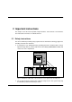
3 Overview This chapter provides information on the configuration levels and the configuration of the S130 Business Server series and the concept of system operation. S130 Business Server Global storage Battery unit Figure 2: S130 Business Server, global storage and battery unit The S130 Business Server comprises two cabinets together with an additional cabinet for channel extensions. Two global storage units can be connected, each of which is located in a separate cabinet.
Configuration levels of the S130 Business Server Overview If the HVZ (high-availability feature) option S130K-1H is available, a defective processor can be replaced with the high-availability processor (the high-availability feature is only available for the models S130-C, S130-E and S130-P). Model Number of processors Performance factor S130-C 2 processing units 1.0 S130-E 3 processing units 1.4 S130-K 4 processing units 1.9 S130-P 6 processing units 2.6 S130-T 8 processing units 3.
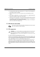
Overview Concept of system operation 3.2 Concept of system operation V7 System operation is described in the chapter “Basics of system operation“ of the “SINIX-2000 V7.0“ [1] manual. The following section lists the most important hardware and software components for S130 operation. 3.2.1 Hardware Secondary console serial Console SKP S130 I/O channel CPU Radio-controlled clock/ GTS ATOP serial LAN serial V.
Concept of system operation ● Overview The service/console processor (3970-SKP) with the SINIX operating system. Operation of the S130 system takes place via a local PC: the 3970-SKP service/console processor. S130 and 3970-SKP communicate with one another in three ways: – – – serial line (V.
Overview Concept of system operation 3.2.2 Software The following software components play an important role in S130 operation: ● Window interface The SINIX operating system is run on the 3970-SKP. One component of SINIX is the window interface based on the X Window system (see the ”SINIX-2000 V7.0” [1] manual). V7 A brief introduction to the window system can be found in the chapter entitled "Brief introduction to the window system" in the "SINIX-2000 V7.0" [1] manual.
Concept of system operation Overview 3.2.3 Authorization control The access to operation of the BS2000, SVP and SINIX system components is protected: ● Access to the BS2000 console If you try to make an entry in a BS2000 control window after the system has been started up for the first time, you will be requested to enter a password. The password is specified when the system is installed and is identical to the password for the corresponding SINIX user ID (e.g. cons0 for the CONS0 console window).
4 Controls and indicators The following controls and indicators are provided for the S130 Business Server: – control panel on the Business Server cabinet, page 12 – control panel on the global storage cabinet, page 12 – EMERGENCY STOP switch, page 19 The S130 is operated using the operator terminals on the service/console processor.
Control panel on the Business Server cabinet Controls and indicators 4.1 Control panel on the Business Server cabinet The control panel is connected with the service processor (SVP) in the S130 Business Server.
Controls and indicators Control panel on the Business Server cabinet Information is displayed on the LCD display in the following format: STATUS CC C CCCC FFFFFFFFFFFFFFFF Line 1 Line 2 T Pnnn DOWN STOP WAIT RUN LOAD Displays in line 1 FFFFFFFFFFFFFFFF Displays in line 2 CM CE Meanings: Line Display field Display Meaning Line 1 Maintenance mode none User mode CE Maintenance mode CM Hot system maintenance mode none Normal mode T Test mode Pnnn S130 switched off: P000 Test mode Clu
Control panel on the Business Server cabinet Controls and indicators POWER COMPLETE This green light illuminates after the system power controller has terminated the switching on sequence without errors. The light is extinguished when the POWER OFF key is pressed. SYSTEM This green light illuminates when the processing units are active. CHECK This yellow light illuminates when the service processor has decoded a machine error or an error in the power supply modules of the Business Server.
Controls and indicators Control panel on the Business Server cabinet 4.1.2 Button functions LCD BACK LIGHT The LCD display STATUS (background) is illuminated for five minutes when you press this button. The lights go out immediately when you press this button again. POWER ON When this button is pressed, the power supply of the entire system is switched on sequentially. The order is predetermined.
Control panel on the global storage cabinet Controls and indicators 4.2 Control panel on the global storage cabinet The control panel is connected to the service processor in global storage.
Controls and indicators Control panel on the global storage cabinet The information is shown on the LCD display in the following format: STATUS CC C CCCC FFFFFFFFFFFFFFFF CM CE Line 1 Line 2 T Pnnn Bnnn CHK CNCT FFFFFFFFFFFFFFFF Displays in line 1 Displays in line 2 Meanings: Line Display field Display Meaning Line 1 Maintenance mode none User mode CE Maintenance mode CM Hot system maintenance mode none Normal mode T Test mode Pnnn SSU switched off, battery not active: P000 SSU swit
Control panel on the global storage cabinet Controls and indicators POWER COMPLETE This green light is lit up after the system power controller has terminated the switching on sequence without any errors. The light is extinguished when the POWER OFF button is pressed. SSU CHECK The display illuminates if there is an error in global storage. The buzzer sounds at the same time.
Controls and indicators EMERGENCY STOP switch 4.3 EMERGENCY STOP switch Not only the Business Server cabinet, but also the global storage and battery cabinets each have an EMERGENCY STOP switch. If the EMERGENCY STOP switch on the S130 is pressed, global storage is also switched off. If you wish to cut power to the entire system, the EMERGENCY STOP switch on the battery cabinet must also be pressed.
Eine Dokuschablone von Frank Flachenecker by f.f.
5 Switching the S130 Business Server on and off This chapter describes the various technical options for switching the S130 Business Server on and off, depending on the hardware. 5.1 Switching the S130 on and off using the control panel Console SKP S130 I/O channel SVP LAN LAN If the SKP is not linked to the S130 via the on/off facility (optional), the S130 must be switched on and off using the control panel.
Switching the S130 on and off using the control panel When both systems are ready, i.e. all windows on the 3970-SKP have been opened and the LCD display on the S130 no longer shows any P codes, you can log in on the SVP (see page 34ff) and start the BS2000 system via PROGRAM LOAD FRAME: DETAIL-1 (see page 51). If a POWER ON IPL is configured, the system is loaded automatically (see page 70 AUXILIARY FRAME: LOAD PRESET1).
Switching the S130 on and off from the SKP c) You can also terminate the SINIX system using the on/off button on the SKP. However, please make note of the following: ! If the SKP is switched off using the button, it sends the command /shutdown or a self-defined /run xxxx command to any running BS2000 system before it switches itself off after a certain wait time has expired. V7 You can define the shutdown command and the length of the wait period using the sysadm forms.
Switching the S130 on and off from the SKP You access the “Switching on / off the host” form via the sysadm menu: Ê Select or open a SINIX screen Ê Login: root or sysadm Ê Enter password Ê For login with root: enter sysadm The SINIX system administration window is displayed.
Switching the S130 on and off from the SKP Ê Select the menu item “host”: Ê Select the menu item “host - The Power ON/OFF of the Host”: U25339-J-Z126-1-7600 25
Switching the S130 on and off from the SKP The “Switching on / off the host” form is displayed: V7 Information on operation of the FMLI interfaces can be found in the “SINIX-2000 V7.0” manual [1]. By entering YES for one of the two questions at the bottom of the form followed by the P2 (CHOICES) key, you can specify whether the S130 can be switched on or off immediately. Press the P3 (SAVE) key after filling out the form. On no account should both questions be answered with YES.
Switching the S130 on and off from the SKP The switching operating is performed after you press the U25339-J-Z126-1-7600 P3 (SAVE) key.
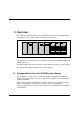
Automatic switching on/off of the S130 via the SKP 5.3 Automatic switching on/off of the S130 via the SKP Console SKP Type-2 channel S130 LAN V.24 SVP COM2 On/off facility LAN To switch the S130 on and off from the SKP, it must have the optional on/off facility. The on/off facility is linked to the SKP via the V.24 interface COM2. You access the “Switching on / off the host” form for switching on or off via the sysadm forms (see also the “SINIX-2000 V7.0“ [1] manual).
Automatic switching on/off of the S130 via the SKP The “Switching on / off the host” form is displayed:´ By entering YES for the two questions at the top of the window, you can specify whether the S130 should be switched on automatically if the 3970-SKP is switched on or SINIX is started on the 3970-SKP, and whether the S130 should be automatically switched off if the SINIX system is shut down or the 3970-SKP is switched off.
Time-driven switching on and off of the SKP and S130 5.4 Time-driven switching on and off of the SKP and S130 The SKP can switch itself and the S130 on and off at a certain time. V7 Definition of the time at which the SKP and the S130 are to be switched on/off, a shutdown command, and the length of the wait time before the SKP and S130 are switched off can be specified using the sysadm forms.
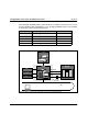
Switching the SKP and S130 on and off using ATOP 3914 5.5 Switching the SKP and S130 on and off using ATOP 3914 Console SKP Type-2 channel S130 ATOP LAN COM2 V.24 SVP On/off facility LAN The S130 can also be switched on automatically using the SKP in conjunction with the ATOP 3914. The optional on/off facility is required for this. Furthermore, the S130 must be configured to switch on and off automatically as part of the starting and shutting down procedure for the SKP.
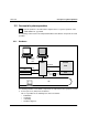
Switching the S130 on and off from a remote system 5.6 Switching the S130 on and off from a remote system DCU 8323 Modem DCU 8323 Modem or Console SKP S130 Type-2 channel ATOP Telephone network LAN COM2 SVP V.24 On/off facility LAN Switching on and off can be carried out from a remote system using a modem/DCU. Information on operating the DCU can be found in the data sheet “8323 Data Communication Unit“ [5]. The optional on/off facility is required.
6 Standard processing in SVP mode Jobs are assigned to the service processor via special SVP menus, so-called SVP frames. All the information you require as an operator working with SVP frames can be found in this chapter. You will find instructions on the use of all user frames in the original “GS8600 MODEL GROUP OPERATORS GUIDE” (FJ-No. C112-E015-01EN). After switching on the S130 and 3970-SKP, BS2000 operation must be prepared, i.e. the BS2000 operating system must be loaded (IPL = Initial Program Load).
Invoking an SVP frame Standard processing in SVP mode 6.1 Invoking an SVP frame By default, an SVP window is configured with the label “SVPST0 #1 (computer name)” to operate the SVP. Figure 7: Overview of the X window system windows (example) You can enter into SVP operator mode at the operating terminal by clicking on the SVPST0 #1 (computer name) window with the left mouse button.
Standard processing in SVP mode Invoking an SVP frame Figure 8: SVPST0 #1 window Ê Select the “Standard partner ($KVPHV0)” function by pressing the “Last connection ($KVPHV0)” by pressing the C key. Confirm with the ENTER key.
Invoking an SVP frame Standard processing in SVP mode The password entry window is displayed: Figure 9: SVPST0 #1 window (password entry) Enter the password for the specified user ID and press Ê ENTER .
Standard processing in SVP mode General frame structure 6.2 General frame structure ---- FRAME XXXXXX: YYYYYY ---- Line Display area 1-21 22-23 24 25 System status messages SVP messages Command entry Hardware status Status displays at the operating terminal Column: 50 51 Figure 10: General structure of an SVP frame Each SVP frame is divided into different areas: Lines 1 - 21 This is the display area of a frame. Here the functions and parameters that may be selected or output are displayed.
General frame structure Standard processing in SVP mode 6.2.1 System status messages in line 22 1 2 3 4 5 6 7 8 .... + .... 0 .... + .... 0 .... + .... 0 .... + .... 0 .... + .... 0 .... + .... 0 .... + .... 0 .... + ....
Standard processing in SVP mode General frame structure Column Symbol Meaning 46 - 55 The system may be in the system down state. This display can also appear when Write-Console messages are output (e.g. SHUTDOWN COMPLETED) and can be deleted with the F3 key. In multiple-cluster operation, the selected cluster is in the stop state. The selected CPU is in the CHECK stop state. The address comparison stop mode is active and the selected CPU is in the address comparison stop state.
General frame structure Standard processing in SVP mode 6.2.2 System status messages in line 23 The following picture shows the extended area of the system status messages in line 23: 1 2 3 4 5 6 7 8 .... + .... 0 .... + .... 0 .... + .... 0 .... + .... 0 .... + .... 0 .... + .... 0 .... + .... 0 .... + ....
Standard processing in SVP mode General frame structure Column Symbol Meaning 74 - 75 none PW The power supply is okay. (Power Warning) An error has occurred in the power supply of the S130. 78 - 80 none CHK No CHK (machine check). A CHK occurred in S130. 6.2.3 Hardware status display in line 24 The following diagram shows the format of the hardware status display in line 24: cccc ...................................
Using frames Standard processing in SVP mode 6.3 Using frames You assign a job to the SVP by invoking the relevant frame, selecting the desired function, and specifying the required parameters. To select a function or specify a parameter, you must enter the alphanumeric characters shown in the frame in the input fields marked by an arrow (=>). The input fields can be selected with the tab key . Once you have entered all the functions and parameters assigned to a job, press the ENTER key.
Standard processing in SVP mode Using frames Overview of the SVP function keys The following overview shows the keys and their functions as valid for most SVP frames. In some SVP frames keys can have another function. This is then shown in the corresponding SVP frame description. Some of the keys shown here only have a function in CE mode (see information below) and are used exclusively by the service department.
Using frames Standard processing in SVP mode PF . . P.. Name Function PF 18 P18 Step Executes the next command if the S130 is in Single Cycle Instruction Mode. PF 19 P19 ARMSS control Changes the user rights of an existing ARMSS connection. PF 20 P20 Stop only in CE mode : stops the selected CPU PF 21 F1 Start Starts the selected CPU PF 22 F2 PF 23 F3 not assigned Mode Select – – – – PF 24 K.. 44 Mode Change K3 Switches to the MODE SELECTION FRAME.
Standard processing in SVP mode Using frames 6.3.2 Switching between user frames A switch between the user frames is only possible within a specified scheme or via an FR command.
User frames Standard processing in SVP mode 6.3.3 Options for switching between frames on the SKP operating terminal The following table shows the options for switching to another frame on the SKP operating terminal. Operation Effect P2 Only in CE mode : by pressing this key you switch from any frame directly to the index frame. The selection of the desired frame can then be made by entering the frame ID in the index frame. P3 Pressing this key (return key) switches back to the previous frame.
Standard processing in SVP mode User frames 6.4.
User frames Standard processing in SVP mode EXECUTION The following functions are executed after the appropriate number is entered in the input fields: The functions are executed according to the entries in the CPU SELECT and STOP/START MODE fields (see table on next page)! ! 1 CPU STOP stops either the CPU selected in the CPU SELECT and STOP/START MODE fields or all CPUs 2 INTERRUPT creates an external interrupt for the CPU(s) selected in the fields CPU SELECT and STOP/START MODE 3 TOD ENABLE
Standard processing in SVP mode User frames Note The following table shows all the functions that can be meaningfully combined: Function CPU STOP INTERRUPT STORE STATUS RESTART TOD ENABLE SYSTEM RESET SYSTEM RESET CLEAR CPU SELECT STOP/START MODE Effect on: 1 All CPU all CPUs 0 ... 7 2 TARGET CPU selected CPU 0 ...
User frames Standard processing in SVP mode 6.4.2 (LD) PROGRAM LOAD FRAME: BASIC ----- PROGRAM LOAD FRAME: BASIC ----- E02L01F -LOAD FUNCTION==> *1 START AUTO *2 START FAST *3 START DIAL *4 START *5 SYSTEM DUMP *ENTER *PF7 *FR AU5 CL-0 CPU-0 CHP-0 EXECUTE GO TO DETAIL-1 GO TO PRESET(AU5 FRAME) RUN M FLAG CODE = F6C0C100 00000F00 TAST LTG Figure 16: PROGRAM LOAD FRAME: BASIC screen An IPL is executed by entering a load function and pressing the ENTER key.
Standard processing in SVP mode 6.4.2.1 User frames (LD) PROGRAM LOAD FRAME: DETAIL-1 ----- PROGRAM LOAD FRAME: DETAIL-1 ----- E02L01F -LOAD FUNCTION-IPL DEVICE==> ==> 2 *1 START AUTO *1 PRESET GROUP ------------------+ *2 START FAST >*2 CURRENT GROUP --------+ | *3 START DIAL *3 UNIT ADDRESS -+ + + *4 START FDE0 FDE0 0214 *5 SYSTEM DUMP XXXX 00B0 *6 LOAD CLEAR -----+ XXXX XXXX *7 LOAD NON CLEAR -+ XXXX XXXX | +MT CONTROL--- DETAIL-2 STATUS --PARMS=> 1 ==> 1 VM MODE : EMOS.
User frames Standard processing in SVP mode 2 CURRENT GROUP 3 UNIT ADDRESS PARMS => Position 1 If IPL is terminated normally, the device address list is transferred from the PRESET GROUP to the CURRENT GROUP. If the IPL is unsuccessful, the next device address from the PRESET GROUP is reloaded. If this loading is terminated normally, this device address heads the CURRENT GROUP. The first device address in this column is the device from which the last IPL was executed.
Standard processing in SVP mode User frames DETAIL-2 STATUS In this position the current settings of the PROGRAM LOAD FRAME: DETAIL-2 are displayed. Check the settings. If they are correct, execute the IPL by pressing ENTER . If not, press the P9 key to correct the entries in PROGRAM LOAD FRAME: DETAIL-2.
User frames 6.4.2.
Standard processing in SVP mode User frames Special key functions ENTER Sets operating mode. If a loading function has previously been stored in PROGRAM LOAD FRAME: DETAIL-1 with the P9 key, an IPL with the set parameters is executed. P3 Switches to PROGRAM LOAD FRAME: BASIC (page 50) P9 Switches to PROGRAM LOAD FRAME: DETAIL-1 (page 51) With the exception of the load function, the parameters entered in the subframes are retained when switching between DETAIL-1 and DETAIL-2-FRAME with the P9 key.
User frames Standard processing in SVP mode ----- STATUS DISPLAY FRAME: SSU ----- SS0 SS1 (SSU0) (SSU1) SSU0 SSU1 PON PON 512MB 512MB ONL CNCT ONL CNCT E02L01F BS BS 512MB 512MB BS BS *PF7 CL-0 CPU-0 CHP-0 CLUSTER FRAME RUN M FLAG CODE = F6C0C100 00000F00 TAST ssu0 LTG Figure 20: STATUS DISPLAY FRAME: SSU screen This displays information on the status of the connected global storage. Memory size, battery status, power status, online status, and connect status are displayed.
Standard processing in SVP mode User frames 6.4.
User frames Standard processing in SVP mode The following table shows the additional entries required for each of the three main functions in other input fields: Input field Function RATE CONTROL UNIT ADRS ADRS TYPE ADRS COMP SELECT ADRS SET ADRS COMP MODE 1 RATE CONTROL o x x x x x 2 ADRS COMP STOP x x o o o o 3 FIRM DUMP x o x x x x o: entry required x: entry not required RATE CONTROL => 1 2 PROCESS I-STEP ADRS TYPE => 1 2 ABSOLUTE LOGICAL ADRS COMP SELECT => 1 2 3 4 5 6
Standard processing in SVP mode User frames ADRS COMP MODE => 1 RESET 2 3 SET NORMAL Address compare stop mode Switches off address compare stop and resets address compare stop conditions in the fields ADRS TYPE, ADRS COMP SELECT and ADRS SET Switches on address compare stop Switches off address compare stop 6.4.
User frames Standard processing in SVP mode FACILITY => Possible displays of memory areas with various addresses: L LOGICAL R REAL P P-VIRTUAL S S-VIRTUAL ABS KEY V A-VIRTUAL I H-VIRTUAL SS SS-REAL SV SS-VRTL ADRS => logical storage address real storage address primary virtual storage address secondary virtual storage address absolute address memory protect key address areas virtual address basic address area´s virtual address SSU real address SSU virtual address Memory address XXXX XXXXXXXX address
Standard processing in SVP mode FUNCTION => A ALTER D DISPLAY FACILITY => GR PSW CR FCR FPR PRX AR XCR GSR EX EPRX ADRS => User frames The following functions are executed after the appropriate letter is entered and ENTER is pressed: change and modify register contents display register contents Possible displays of registers: General register Program status word Control register Feature control register Floating-point register Prefix register Access register Extended control register Global scope registe
User frames Standard processing in SVP mode 6.4.
Standard processing in SVP mode User frames 6.4.7 (CH) CH/SUBCH STATUS DISPLAY FRAME: CHANNEL ----- CH/SUBCH STATUS DISPLAY FRAME: CHANNEL ----CHP 0 E02L01F PCHAD 0000000000000000 1111111111111111 2222222222222222 3333333333333333 0123456789ABCDEF 0123456789ABCDEF 0123456789ABCDEF 0123456789ABCDEF CHPID 0000000000000000 1111111111111111 2222222222222222 3333333333333333 0123456789ABCDEF 0123456789ABCDEF 0123456789ABCDEF 0123456789ABCDEF INSTALLED OP ON-LINE CH-TYPE IF-TYPE ****....****.... ****....**.
User frames Standard processing in SVP mode LINKADR => 01 00 ... FE link address for type-S channel without director with director: output port address = link address LCUADR => logische control unit address no input required PCHAD => 00 ... FF physical channel address Special key functions 64 P10 Display of channel processor with next lower number. P11 Display of channel processor with next higher number.
Standard processing in SVP mode User frames 6.4.8 (AU) AUXILIARY FRAME: MENU ----- AUXILIARY FRAME: MENU ----- E02L01F SELECTION=> *1 REAL CLOCK *2 IORSF CONTROL *3 RELATED SCB *4 P-OFF/IMPL *5 LOAD PRESET *7 CONFIGURATION CL-0 CPU-0 CHP-0 RUN M FLAG CODE = F6C0C100 00000F00 TAST LTG Figure 26: AUXILIARY FRAME: MENU screen You can move to other frames by making entries in this menu frame and pressing SELECTION => 1 2 3 4 5 7 U25339-J-Z126-1-7600 ENTER .
User frames 6.4.8.1 Standard processing in SVP mode (AU1) AUXILIARY FRAME: REAL CLOCK ----- AUXILIARY FRAME: REAL CLOCK ----- YYYY MM DD 1997.05.21 E02L01F HH MM SS 15:26:47 *PF6 *PF12 CL-0 CPU-0 CHP-0 CANCEL TIMER SET RUN M FLAG CODE = F6C0C100 00000F00 TAST LTG Figure 27: AUXILIARY FRAME: REAL CLOCK screen When the screen is invoked, the current date and time of the SVP are displayed. Press the K1 key before making an entry. Corrections can be entered in the line below.
Standard processing in SVP mode 6.4.8.2 User frames (AU2) AUXILIARY FRAME: IORSF CONTROL ----- AUXILIARY FRAME: IORSF CONTROL ----NO. 0 1 P 2 P 3 E02L01F COMMENT S130TA1 // \UGENDATA.HW.S130.TA1.OSD.S130TA1 / DATE 1997.04.30 TIME 16:00 S130TA1X // \UGENDATA.HW.S130.TA1.OSD.S130TA1X DATE 1997.04.30 TIME 16:07 S130TA1 // \UGENDATA.HW.S130.TA1.OSD.S130TA1 / DATE 1997.05.14 TIME 15:20 S130TA1X // \UGENDATA.HW.S130.TA1.OSD.S130TA1X DATE 1997.05.14 TIME 15:43 FUNCTION=> *1 SET NO *2 PROTECT *3 SWAP 07.
User frames Standard processing in SVP mode SPECIFY SWAP NO. <=> Enter two file numbers which are to be swapped. You can only make entries if you select function 1 beforehand. Special key functions 6.4.8.3 P8 Sets 4 to 7 are displayed P7 Sets 0 to 3 are displayed (AU3) AUXILIARY FRAME: RELATED SCB’S i This frame is intended exclusively for use by the service department.
Standard processing in SVP mode 6.4.8.4 User frames (AU4) AUXILIARY FRAME: P-OFF/IMPL ----- AUXILIARY FRAME: P-OFF/IMPL ----- E02L01F FUNCTION=> *1 POWER OFF *2 IMPL CL-0 CPU-0 CHP-0 RUN M FLAG CODE = F6C0C100 00000F00 TAST LTG Figure 30: AUXILIARY FRAME: P-OFF/IMPL screen By making an entry in this frame and pressing initialize it.
User frames 6.4.8.
Standard processing in SVP mode 1 2 User frames ENABLE DISABLE automatically executes IPL after IMPL does not execute IPL, i.e. IPL must be triggered manually using PROGRAM LOAD FRAME: BASIC or PROGRAM LOAD FRAME: DETAIL-1. INITIAL FRAME => Here you can set the display form of the PROGRAM LOAD FRAME.
User frames Standard processing in SVP mode EXA MODE => 1 2 Selection of addressing mode ENABLE DISABLE START IPL NO => 1 2 FIX(1) CURRENT extended XA mode not used on the S130 Business Server Selection of the IPL Start Mode number Start Mode number 1 (automatic start) Start Mode number of most recently executed IPL. Special key functions 6.4.8.
Standard processing in SVP mode FUNCTION => User frames The following functions are carried out by entering the appropriate number: 1 2 DISPLAY CFR INIT CFR FILE NO. 3 DISPLAY FILE X EXECUTE displays current configuration activates selected FILE after IMPL, enter a number in the INIT CFR FILE NO. => field displays configuration file, enter a number in the CFR FILE NO. => field executes the last function entered INIT CFR FILE NO. => Selection of a configuration file for function 2 CFR FILE NO.
User frames Standard processing in SVP mode 6.4.9 (MF) MSF FRAME ----- MSF FRAME: FLAG CODE LOG DISPLAY ----INITIALIZED 1997.02.
Standard processing in SVP mode User frames Frame line 24: You can switch to FLAG code entries of other components by making the following entries in line 24: ssu0: FLAG code entries of SSU0 ssu1: FLAG code entries of SSU1 self: back to the FLAG code entries of the cluster ----- MSF FRAME: FLAG CODE LOG DISPLAY ----- E02L01F INITIALIZED 1997.02.
User frames Standard processing in SVP mode 6.4.
Standard processing in SVP mode Selecting IORSF 6.5 Examples of standard processing in SVP mode 6.5.1 Selecting IORSF The steps listed below are conditions for the loading of a particular IORSF at the next IMPL or the next time the system is switched on. In the following example the IORSF is selected with Level 2. Conditions You must have selected the “SVPST0 #1 (computer name)” window, created a link to the $KVPHV0, and entered the correct password.
Selecting IORSF Standard processing in SVP mode The AUXILIARY FRAME: MENU screen is displayed ----- AUXILIARY FRAME: MENU ----- E02L01F SELECTION=> *1 REAL CLOCK *2 IORSF CONTROL *3 RELATED SCB *4 P-OFF/IMPL *5 LOAD PRESET *7 CONFIGURATION CL-0 CPU-0 CHP-0 RUN M FLAG CODE = F6C0C100 00000F00 TAST LTG Figure 37: AUXILIARY FRAME: MENU screen Invoking IORSF Control Frame Enter 2 in the SELECTION=> field. Press Ê i 78 ENTER .
Standard processing in SVP mode Selecting IORSF The AUXILIARY FRAME: IORSF CONTROL screen is displayed: ----- AUXILIARY FRAME: IORSF CONTROL ----NO. 0 1 P 2 P 3 E02L01F COMMENT S130TA1 // \UGENDATA.HW.S130.TA1.OSD.S130TA1 / DATE 1997.04.30 TIME 16:00 S130TA1X // \UGENDATA.HW.S130.TA1.OSD.S130TA1X DATE 1997.04.30 TIME 16:07 S130TA1 // \UGENDATA.HW.S130.TA1.OSD.S130TA1 / DATE 1997.05.14 TIME 15:20 S130TA1X // \UGENDATA.HW.S130.TA1.OSD.S130TA1X DATE 1997.05.
Activating IORSF Standard processing in SVP mode 6.5.2 Activating IORSF The set IORSF must be activated with a IMPL: Conditions You must be in the AUXILIARY FRAME: IORSF CONTROL screen. Ê Press Ê Enter 4 in the SELECTION=> field. Press P3 to switch back to the AUXILIARY FRAME: MENU. ENTER .
Standard processing in SVP mode PROGRAM LOAD FRAME PRESET1 6.5.3 Setting up PROGRAM LOAD FRAME PRESET1 In this example, you specify: ● LOAD function 1 with the name AUTO (AUTO=Automatic Startup) for a POWER ON IPL ● Device number of the IPL device to be used for a POWER ON IPL (current: 0108) ● Automatic IPL after a POWER ON ● The LOAD FRAME should always be displayed as PROGRAM LOAD FRAME: DETAIL1.
PROGRAM LOAD FRAME PRESET1 Standard processing in SVP mode The AUXILIARY FRAME: LOAD PRESET1 screen is displayed: ----- AUXILIARY FRAME: LOAD PRESET1 -----START MODE==> 1 *1 START AUTO *2 START FAST >3 START DIAL *4 START E02L01F -IPL DEVICE1 PRESET GROUP -----------------+ 2 CURRENT GROUP --------+ | 3 UNIT ADDRESS -+ + + A108 A108 0108 XXXX XXXX XXXX XXXX XXXX XXXX -POWER ON IPL==> 1 *1 ENABLE >2 DISABLE -INITIAL FRAME==> 2 *1 LOAD FRAME(BASIC) >2 LOAD FRAME(DETAIL) CL-0 *PF12 *PF9 CPU-0 CHP-0 CATA
Standard processing in SVP mode PROGRAM LOAD FRAME PRESET2 6.5.4 Setting up PROGRAM LOAD FRAME PRESET2 In the PROGRAM LOAD FRAME PRESET2 you specify which operating mode is to be set after the S130 system is switched on. The following are specified in the example below: ● ● ● VM2000 operating mode EXA mode Automatic startup of the operating system Conditions You must be in the AUXILIARY FRAME: LOAD PRESET1 screen.
IPL in PROGRAM LOAD FRAME: DETAIL-1 Standard processing in SVP mode Catalog parameters Ê Press the P12 key. The values entered are saved and thus made known to the SVP. These settings are accessed for each IPL. 6.5.5 Executing IPL in PROGRAM LOAD FRAME: DETAIL-1 The IPL can be executed manually 1according to the setting using PROGRAM LOAD FRAME DETAIL-1.
Standard processing in SVP mode IPL in PROGRAM LOAD FRAME: DETAIL-1 In this example, the PROGRAM LOAD FRAME: DETAIL-1 screen is displayed: ----- PROGRAM LOAD FRAME: DETAIL-1 ----- E02L01F -LOAD FUNCTION-IPL DEVICE==> 3 ==> 3 *1 START AUTO *1 PRESET GROUP ------------------+ *2 START FAST >*2 CURRENT GROUP --------+ | *3 START DIAL *3 UNIT ADDRESS -+ + + *4 START A108 A108 0108 *5 SYSTEM DUMP XXXX XXXX *6 LOAD CLEAR -----+ XXXX XXXX *7 LOAD NON CLEAR -+ XXXX XXXX | +MT CONTROL--- DETAIL-2 STATUS --PARMS=
IPL in PROGRAM LOAD FRAME: DETAIL-1 DETAIL-2 STATUS Standard processing in SVP mode The settings in DETAIL-2 FRAME are displayed in detail. Check the settings. If they are correct, execute the IPL (see below), if not, correct the entries in DETAIL-2 FRAME (see section “Setting operating mode via PROGRAM LOAD FRAME: DETAIL-2” on page 87). In our example VM MODE: NATIVE, i.e. the firmware for the BS2000 operation is loaded. This setting must be changed in DETAIL-2 FRAME for this example.
Standard processing in SVP mode Setting operating mode 6.5.6 Setting operating mode via PROGRAM LOAD FRAME: DETAIL-2 The operating mode can be reset using the PROGRAM LOAD FRAME: DETAIL-2. This selects the appropriate firmware for running BS2000 or VM2000. The following are specified in the example below: ● VM2000 operating mode ● executing IPL after reloading the firmware Conditions You must be in the PROGRAM LOAD FRAME: DETAIL-1 screen.
Setting operating mode Standard processing in SVP mode Activating settings Ê After you have checked all the settings, press ENTER . The following prompt appears: *********************************** * * * ARE YOU SURE ? (ENTER Y OR N) N * * * *********************************** Press ENTER 88 Y to execute the IPL or N to cancel the procedure. Confirm your input with .
7 Operating the BS2000 console Selecting the console window At the operator terminal, you enter system operating mode by clicking the window CONS0 #1 with the left mouse button. System operation When the BS2000 console window is opened, no input is permitted. If you attempt to make an entry, you are prompted to release the window by entering the valid password. You do this using the MENU function.
Eine Dokuschablone von Frank Flachenecker by f.f.
8 Troubleshooting This chapter describes what to do out in case of malfunction. Problems with the S130 page 91 Displays if there is a hardware error page 92 Carrying out a system dump page 93 Measures to take if there is an I/O processor failure page 93 Measures to take if there is a processing computer failure page 94 Problems with the service/console processor (SKP) page 97 8.
Problems with the S130 Troubleshooting 8.1.1 Displays in the case of a hardware error The S130 informs you of hardware errors in the following manner: ● On the S130 control panel If the yellow CHECK light illuminates, there may be a hardware error. At the same time, the FLAG code appears on the LCD display. This can indicate an error in the service processor or a machine error.
Troubleshooting Problems with the S130 8.1.2 Carrying out a system dump Conditions: 1. Select the SVPST0 window 2. Select LD PROGRAM LOAD FRAME 3. Select LOAD FUNCTION => 5 (SYSTEM DUMP) The system dump stored on hard disk or cassette by the DUMP program is required for error diagnosis. Afterwards, the BS2000/VM2000 system must be reloaded with the IPL. Information on SLED operation can be found in the “Introductory Guide to Systems Support“ [6] manual. i 8.1.
Problems with the S130 Troubleshooting List of I/O channels: IOP0 (channel processor CHP 0 and 1) channel range 00 to 7F IOP1 (channel processor CHP 2 and 3) channel range 80 to FF If the first I/O processor (IOP0) fails, system operation is no longer possible due to the lack of a console. If a logical console which works via the front-end processor and a functioning channel exists, the system can still be used. Execute IMPL and IPL after system crash with the defective I/O processor disabled by the SVP.
Troubleshooting Ê Problems with the S130 Once the message SHUTDOWN COMPLETED is displayed, switch the S130 to CE mode by switching the CE key on the inside of the maintenance panel of the S130 to the position “Maintenance Mode On”. The CE mode is indicated by the display CE on the control panel of the S130 (see page 12f) and in line 23 of the SVPST0 window on the SKP operating terminal (see page 40). Ê Select the SVPST0 window on the SKP operating terminal (see page 36).
Problems with the S130 Troubleshooting Ê Press the Ê Select the frame AU4 by entering the frame code AU4 and press the Ê Select the IMPL function by entering 2 (IMPL activates the new setting) and confirm your input by pressing the ENTER key. P2 key to return to the Index Frame. Respond to the following prompt with Y and confirm by pressing the ENTER ENTER key. key.
Troubleshooting Problems with the service/console processor (SKP) 8.2 Problems with the service/console processor (SKP) If you have problems with the SKP, contact the service department and discuss the steps to be taken. Depending the outcome of this discussion, you may be required to do the following: 1. Reboot the SINIX system. Make sure that applications under SINIX, e.g. sysadm, have been terminated.
Important key combinations Troubleshooting 8.3 Important key combinations If your mouse is not working, you can use the keys windows of the X-Windows window system.
Related publications Please apply to your local office for ordering the manuals. [1] SINIX-2000 V7.0 Installation, Operation and Administration User Guide Target group This manual is intended for privileged users (operators, system administrators) of the service/console processor 3970-SKP, the channel adapter 3970-KAx, and the business servers C80-2 and SR2000.
Related publications [4] TELESERVICE - TSB2000 (BS2000/OSD Server) User Guide Target group The manual addresses the operating personnel of the C50, C70, C80, H100, S110, S130 and SR2000 mainframes. Knowledge of BS2000 and basic SINIX knowledge are required to operate TELESERVICE. Contents Service technicians use TELESERVICE to support, maintain and perform fault diagnostics on customer systems from the TELESERVICE center.
Index A ALTER/DISPLAY FRAME (AD) 59 ALTER/DISPLAY FRAME (subframe) 60 ATOP 8 switching the S130 on/off 31 authorization control 10 AUTO 81 AUXILIARY FRAME IORSF CONTROL 79 LOAD PRESET1 82 LOAD PRESET2 83 MENU 78 MENU (AU) 65 P-OFF/IMPL 80 AUXILIARY FRAME (AU1): REAL CLOCK 66 AUXILIARY FRAME (AU2): IORSF CONTROL 67 AUXILIARY FRAME (AU3): RELATED SCB’S (only service department) AUXILIARY FRAME (AU4): P-OFF/IMPL 69 AUXILIARY FRAME (AU5): LOAD PRESET1 70 AUXILIARY FRAME (AU5): LOAD PRESET2 71 AUXILIARY FRAME (A
Index D display hardware errors 92 hardware status 41 displays in line 24 41 in line 25 41 E emergencies 3 EMERGENCY STOP switch 19 battery cabinet 19 global storage 19 executing IPL in DETAIL-1 FRAME F form - switching on/off the host frame code 45 frame name 45 frame structure 37 G global storage control panel button functions 18 function of the indicators 84 26 16 H hardware errors, display 92 hardware status, display 41 high-availability CPU activate 94 HVZ (high-availability feature) 6 I I/O proce
Index L line 22 + 23, messages line 23, messages 40 line 24, displays 41 line 25, displays 41 loading BS2000 33 loading IORSF 77 38 M manual IPL 84 MANUAL OPERATION FRAME (MA) 57 manufacturer instructions 4 MCU (Memory Control Unit) 96 MCU defective 96 MESSAGE FRAME (ME) 62 messages in line 22 + 23 38 messages in line 23 40 MODE SELECTION FRAME 77 MODE SELECTION FRAME (ML) 47 MSF FRAME (MF) 74 O operating frames 42 operating mode 83 setting 87 operation hours counter 14 operation of the S130 hardware com
Index S S130 control panel 12 button functions 15 function of the indicators 12 safety instructions 3 SCI (System Control Interface) 96 SCI defective 96 screen AUXILIARY FRAME IORSF CONTROL 79 LOAD PRESET1 82 LOAD PRESET2 83 MENU 78 P-OFF/IMPL 80 MODE SELECTION FRAME 47, 77 PROGRAM LOAD FRAME 85 DETAIL-1 85 DETAIL-2 87 selecting IORSF 77 service/console processor defective 97 setting operating mode 87 setting up PROGRAM LOAD FRAME PRESET1 81 PROGRAM LOAD FRAME PRESET2 83 SSU FRAME 56 starting IMPL 33 STATU
Index automatically 28 by hand 21 from a remote system 32 from SKP 23 time-driven 30 using the control panel 21 system components defective 96 system operation 7 system status messages 40 U user frames 46 switching between 45 X X window system windows U25339-J-Z126-1-7600 34 105
Eine Dokuschablone von Frank Flachenecker by f.f.
Contents 1 1.1 1.2 1.3 Introduction . . . . . . . . . . . . . . . . . . . . . . . . . . . . . . . . . . . . . . . . . . . . . . . . . . . . . . . . . . Objectives and target group . . . . . . . . . . . . . . . . . . . . . . . . . . . . . . . . . . . . . . . . . . . . . . . Summary of contents . . . . . . . . . . . . . . . . . . . . . . . . . . . . . . . . . . . . . . . . . . . . . . . . . . . . Notational conventions . . . . . . . . . . . . . . . . . . . . . . . . . . . . . . . . . . . . . . . . . . . . .
Contents 6 6.1 6.2 6.2.1 6.2.2 6.2.3 6.2.4 6.3 6.3.1 6.3.2 6.3.3 6.4 6.4.1 6.4.2 6.4.2.1 6.4.2.2 6.4.3 6.4.4 6.4.5 6.4.6 6.4.7 6.4.8 6.4.8.1 6.4.8.2 6.4.8.3 6.4.8.4 6.4.8.5 6.4.8.6 6.4.9 6.4.10 6.5 6.5.1 6.5.2 6.5.3 6.5.4 6.5.5 6.5.6 Standard processing in SVP mode . . . . . . . . . . . . . . . . . . . . . . . . . . . . . . . . . . . . . . Invoking an SVP frame . . . . . . . . . . . . . . . . . . . . . . . . . . . . . . . . . . . . . . . . . . . . . . . . . General frame structure . . . . . . . . . . . .
Contents 8 8.1 8.1.1 8.1.2 8.1.3 8.1.4 8.1.5 8.2 8.3 Troubleshooting . . . . . . . . . . . . . . . . . . . . . . . . . . . . . . . . . . . . . . . . . . . . . . . . . . . . . . Problems with the S130 . . . . . . . . . . . . . . . . . . . . . . . . . . . . . . . . . . . . . . . . . . . . . . . . . Displays in the case of a hardware error . . . . . . . . . . . . . . . . . . . . . . . . . . . . . . . . . . . . Carrying out a system dump . . . . . . . . . . . . . . . . . . . . . . . . . . . . . . . . . . . .
Eine Dokuschablone von Frank Flachenecker by f.f.
S130 Business Server Operating Manual Target group The manual addresses privileged users (operators, system administrators) of the S130 Business Server. Contents The manual describes the hardware of the S130 Business Server insofar as it is required for system operation. In addition, all SVP frames are described which are of interest for system administration. Edition: Jume 1997 File: S130.PDF BS2000 is a registered trademark of Siemens Nixdorf Informationssyteme AG.