
User's Guide
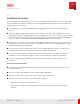
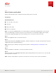
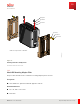
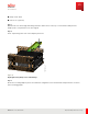
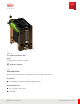
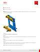
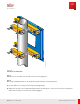
Table Of Contents
- User Guide
- Contents
- Preface
- 1 About this Guide
- 2 Overview
- 3 RU Hardware Feature
- 3.1 System Configuration
- 3.2 RU Specifications
- 3.3 Environment Specifications
- 3.4 RU Downlink/Uplink Default Parameters
- 3.5 Antenna Configuration
- 3.6 Carrier Configuration
- 3.7 Block Diagram
- 3.8 External Interface
- 3.9 TX Control Function
- 3.10 Performance Requirement
- 3.11 Mechanical Design and Other Options
- 4 Ordering Information
- 5 Installation
- 6 Operations
- 7 Maintenance and Trouble Clearing
- 8 Removal
- A References
- B ZTP Overview
- C Optical Connector Cleaning
- D Glossary
- Index

FNC001609_Rev_01
Figure 21
Pole M ount Crossmembers
Step 5
Add jam nuts to each M 10 x 30 mm bolts and secure until tightened.
Step 6
Place large insulating bushings on the wall plate by performing the following substeps:
a) Peel the adhesive covering off of the large insulating bushings.
b) Align the sticky side of the insulating bushings with the threaded holes on the lower front lip of the wall plate
and stick them in place as shown in the following graphic.
Installation
RU Installation
88
Release 1.0 · Issue 1, March 2021
Fujitsu and Fujitsu Customer Use Only