
User's Guide

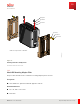
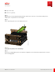
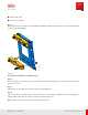
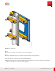
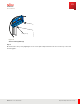
Table Of Contents
- User Guide
- Contents
- Preface
- 1 About this Guide
- 2 Overview
- 3 RU Hardware Feature
- 3.1 System Configuration
- 3.2 RU Specifications
- 3.3 Environment Specifications
- 3.4 RU Downlink/Uplink Default Parameters
- 3.5 Antenna Configuration
- 3.6 Carrier Configuration
- 3.7 Block Diagram
- 3.8 External Interface
- 3.9 TX Control Function
- 3.10 Performance Requirement
- 3.11 Mechanical Design and Other Options
- 4 Ordering Information
- 5 Installation
- 6 Operations
- 7 Maintenance and Trouble Clearing
- 8 Removal
- A References
- B ZTP Overview
- C Optical Connector Cleaning
- D Glossary
- Index

■ Philips screw driver
■ Power tools (optional)
Step 1
Attach both large crossmembers to the Wall M ounting Plate using M 10 x 80 mm bolts, nuts, and flat washers as
shown in the following figure.
FNC001606_Rev_01
Figure 20
Attach Large Crossmembers to W all M ount Plate
Step 2
Secure the large crossmembers to the mounting plate until tightened using a 7/ 16 socket for the bolts and a 5/ 8
wrench for the nuts.
Step 3
Add jam nuts to each M 10 x 80 mm bolts and secure until tightened.
Step 4
Connect the small crossmembers from opposite side of pole to the large crossmembers on the mounting plate
using four M 10 x 30 mm bolts, washers, and nuts as shown in Figure 25.
Note: Fujitsu recommends a second person assist with this step.
Installation
RU Installation
87
Release 1.0 · Issue 1, March 2021
Fujitsu and Fujitsu Customer Use Only