
User's Guide
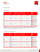
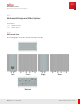
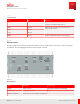


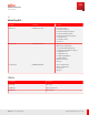
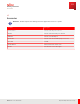
Table Of Contents
- User Guide
- Contents
- Preface
- 1 About this Guide
- 2 Overview
- 3 RU Hardware Feature
- 3.1 System Configuration
- 3.2 RU Specifications
- 3.3 Environment Specifications
- 3.4 RU Downlink/Uplink Default Parameters
- 3.5 Antenna Configuration
- 3.6 Carrier Configuration
- 3.7 Block Diagram
- 3.8 External Interface
- 3.9 TX Control Function
- 3.10 Performance Requirement
- 3.11 Mechanical Design and Other Options
- 4 Ordering Information
- 5 Installation
- 6 Operations
- 7 Maintenance and Trouble Clearing
- 8 Removal
- A References
- B ZTP Overview
- C Optical Connector Cleaning
- D Glossary
- Index

Table 26
Size Information
Item Size Description
Volume 35L Volume calculation does not include connectors,
protrusions, or manufacturing tolerances.
Width 400 mm Dimensions do not include connector, protrusions, or
manufacturing tolerances.
Height 380 mm
Depth 230 mm
Weight 34.0 kg Except mounting bracket, handle, connector guard
3.11.2
Bottom Layout
The RU is installed on the back of the antenna, with the four 4.3-10 RF connectors at bottom of RU connecting to
the antenna. The following figure shows the bottom layout of the RU.
Port#A
DC -48V
RET
Port#B
Port#C
eCPRI
M aintenance
W indow
Port#D
Figure 11
Bottom Layout
Name Description Connector type
DC-48 V Power connector Amphe-BTS compatible (10-761296-Z2S)
Port #1 to #8 Antenna port #A to #D 4.3-10
M aintenance Window M aintenance interface, waterproof by M TW cover.
RU Hardware Feature
Mechanical Design and Other Options
64
Release 1.0 · Issue 1, March 2021
Fujitsu and Fujitsu Customer Use Only