
User's Guide
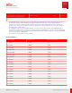
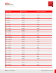
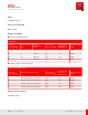
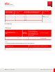
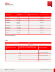
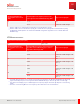
Table Of Contents
- User Guide
- Contents
- Preface
- 1 About this Guide
- 2 Overview
- 3 RU Hardware Feature
- 3.1 System Configuration
- 3.2 RU Specifications
- 3.3 Environment Specifications
- 3.4 RU Downlink/Uplink Default Parameters
- 3.5 Antenna Configuration
- 3.6 Carrier Configuration
- 3.7 Block Diagram
- 3.8 External Interface
- 3.9 TX Control Function
- 3.10 Performance Requirement
- 3.11 Mechanical Design and Other Options
- 4 Ordering Information
- 5 Installation
- 6 Operations
- 7 Maintenance and Trouble Clearing
- 8 Removal
- A References
- B ZTP Overview
- C Optical Connector Cleaning
- D Glossary
- Index

BS channel bandwidth of the
lowest/ highest carrier received
(M Hz)
1
Interfering signal centre frequency offset from the
lower/ upper Base Station RF Bandwidth edge (M Hz)
2
Type of interfering signal
3
20 ±7.395 CW
±17.5 5 M Hz DFT-s-OFDM NR signal
1
1
Number of RBs is 25 for 15 kHz subcarrier spacing and 10 for 30 kHz subcarrier spacing.
2
Number of RBs is 100 for 15 kHz subcarrier spacing, 50 for 30 kHz subcarrier spacing and 24 for 60 kHz subcarrier spacing.
3
The RBs shall be placed adjacent to the transmission bandwidth configuration edge which is closer to the Base Station RF
Bandwidth edge.
Table 23
Narrowband Intermodulation
M ean power of interfering signals [dBm] NF
–52 NF
REF
+ 6 dB
BS channel bandwidth of the
lowest/ highest carrier received
(M Hz)
1, 2
Interfering RB centre frequency offset from the lower/
upper Base Station RF Bandw idth edge or sub-block
edge inside a sub-block gap (kHz)
3
Type of interfering signal
5 ±360 CW
±1420 5 M Hz DFT-s-OFDM NR signal, 1 RB
(Note 1)
10 ±370 CW
±1960 5 M Hz DFT-s-OFDM NR signal, 1 RB
(Note 1)
15
2
±380 CW
±1960 5 M Hz DFT-s-OFDM NR signal, 1 RB
(Note 1)
20
2
±390 CW
±2320 5 M Hz DFT-s-OFDM NR signal, 1 RB
(Note 1)
1
Interfering signal consisting of one resource block positioned at the stated offset, the BS channel bandwidth of the interfering
signal is located adjacently to the lower/ upper Base Station RF Bandwidth edge or sub-block edge inside a sub-block gap.
2
This requirement shall apply only for a G-FRC mapped to the frequency range at the channel edge adjacent to the interfering
signals.
3
The centre of the interfering RB refers to the frequency location between the two central subcarriers.
RU Hardware Feature
Performance Requirement
60
Release 1.0 · Issue 1, March 2021
Fujitsu and Fujitsu Customer Use Only