
User's Guide
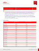
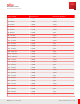
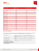
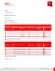
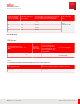
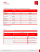
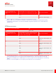
Table Of Contents
- User Guide
- Contents
- Preface
- 1 About this Guide
- 2 Overview
- 3 RU Hardware Feature
- 3.1 System Configuration
- 3.2 RU Specifications
- 3.3 Environment Specifications
- 3.4 RU Downlink/Uplink Default Parameters
- 3.5 Antenna Configuration
- 3.6 Carrier Configuration
- 3.7 Block Diagram
- 3.8 External Interface
- 3.9 TX Control Function
- 3.10 Performance Requirement
- 3.11 Mechanical Design and Other Options
- 4 Ordering Information
- 5 Installation
- 6 Operations
- 7 Maintenance and Trouble Clearing
- 8 Removal
- A References
- B ZTP Overview
- C Optical Connector Cleaning
- D Glossary
- Index

M odulation Quality
Table 15
Error Vector M agnitude (EVM )
M odulation Scheme Required EVM Test tolerance
QPSK ≤ 17.5% 1.0%
16QAM ≤ 12.5%
64QAM ≤ 8%
256QAM ≤ 3.5%
Dynamic Range
Table 16
Total Pow er Dynamic Range (15 kHz SCS)
BS channel bandwidth (M Hz) Total Power Dynamic Range Test tolerance
5 ≥ 13.9 dB 0.4 dB
10 ≥ 17.1 dB
15 ≥ 18.9 dB
20 ≥ 20.2 dB
Table 17
RE (Resource element) Power Control Dynamic Range
M odulation scheme used on the RE
RE power control dynamic range
Down Up
QPSK (PDCCH) – 6 dB +4 dB
QPSK (PDSCH) – 6 dB +3 dB
16QAM PDSCH – 3 dB +3 dB
64QAM PDSCH 0 dB 0 dB
256QAM PDSCH 0 dB 0 dB
Note: Total TX power shall always be less or equal to maximum base station output power.
RU Hardware Feature
Performance Requirement
54
Release 1.0 · Issue 1, March 2021
Fujitsu and Fujitsu Customer Use Only